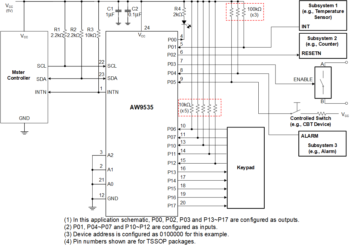
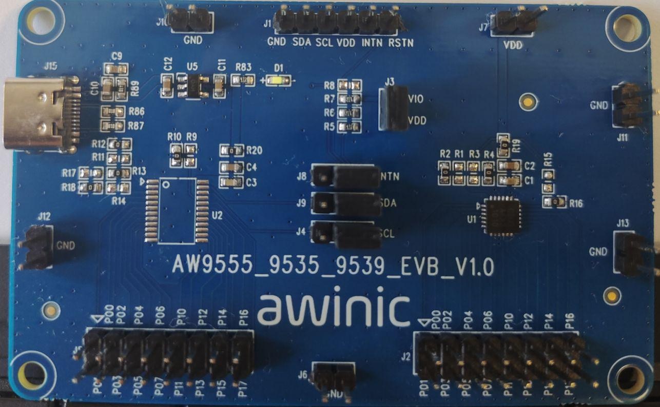
Features
1 16-bit I/O expander
2 I2C bus and SMBus compatible
3 Open-drain active-low interrupt output
4 400kHz I2C interface
5 1.65V~5.5V power supply
6 Configurable slave address with 3 address pins
7 Polarity inversion register
8 Low standby current consumption of 0.7μA (typical at 3.3V VCC)
9 No glitch on power-up
10 5.5V tolerant I/O ports
11 Noise filter on SCL/SDA inputs
12 Latched outputs with high-current drive capability for directly driving LEDs
13 Each I/O can be configured as an input or an output independently, default input
1) AW9555: I/O ports with an internal weak pull-up resistors
2) AW9535: I/O ports without an internal weak pull-up resistors
14 Operation temperature range: -40°C~105°C
15 Package
1) AW9535QNR: QFN 4X4-24L
2) AW9535TSR: TSSOP-24L
3) AW9555TSR: TSSOP-24L
4) AW9555QNR: QFN 4X4-24L
Description
AW9535/AW9555 is a 16-bit I/O expander that can be controlled through the I2C bus. It provides general-purpose remote I/O expansion for most microcontroller families via the I2C interface.
The AW9535/AW9555 consists of two 8-bit Configuration (input or output selection), Input Port, Output Port, and Polarity Inversion (active high or active low operation) registers. At power on, all the 16 I/O ports are configured as inputs. The system master can configure each I/O as an input or an output independently by writing to the I/O configuration bits. The data for each input or output is kept in the corresponding Input or Output register. The Polarity Inversion register can invert the polarity of the Input Port register.
The AW9535/AW9555 open-drain interrupt output is activated when any input state differs from its corresponding input port register state and is used to indicate to the system master that an input state has changed. The power-on reset sets the registers to their default values and initializes the device state machine.
Three hardware pins (A0, A1, A2) vary the fixed I2C-bus address and allow up to eight devices to share the same I2C-bus/SMBus. All I/O pins are 5V tolerant.
The AW9535 is identical to the AW9555, except for the removal of the internal I/O pull-up resistor, which greatly reduces power consumption when the I/Os are held low.