In today's
world, where smartphones have largely replaced handheld cameras, photography
has become one of the most essential use cases for users. As a core technology
affecting the shooting experience, camera image stabilization not only
determines image clarity but also profoundly influences how consumers record
their lives and create content, making it a critical factor in smartphone
purchasing decisions. This document systematically introduces the core
principles, structural classifications, performance parameters, advantages, and
disadvantages of piezoelectric motors, with a focus on their application
scenarios in consumer electronics, precision optics, industrial manufacturing,
medical devices, and other fields.
Piezoelectric
Motor Applications
Piezoelectric
motors are primarily used in the telephoto and macro lenses of high-end
flagship smartphones, leveraging nanometer-level positioning accuracy to
achieve lossless zoom and high-definition macro photography. Some high-end
smart wearable devices and action cameras also employ piezoelectric motors,
utilizing their non-magnetic interference characteristics to avoid affecting
sensor operation and enhance shooting stability.
In addition,
in the precision optics and optoelectronics industry, piezoelectric motors are
the preferred core components, relying on ultra-high positioning accuracy and
non-magnetic interference advantages. They are used in fiber-optic coupling
calibration, optical microscope stage displacement adjustment, laser optical
path fine-tuning, and spectrometer lens positioning. In the field of optical
fiber communications, piezoelectric motors can precisely control fiber
alignment displacement to reduce optical signal loss; in scientific optical
instruments, they enable nanometer-scale optical path calibration to meet
high-precision experimental testing requirements. VCM (Voice Coil Motor) motors
are more commonly used in ordinary optical inspection equipment and simple
optical path adjustment devices.
Working
Principle of Piezoelectric Motors
The piezoelectric
effect is a unique characteristic of piezoelectric materials. When a
piezoelectric material deforms under external force, polarization occurs
internally, and positive and negative charges related to the pressure appear on
its two opposite surfaces (this characteristic can be used to detect the
magnitude of external pressure), as shown in the figure below:
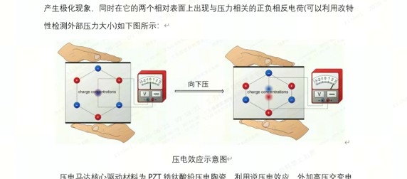
Figure 1
Schematic diagram of the piezoelectric effect (Image source: Toutiao @罗罗日记luoluonotes)
The core
driving material of piezoelectric motors is PZT (lead zirconate titanate)
piezoelectric ceramics. Utilizing the inverse piezoelectric effect, when a
high-voltage alternating voltage is applied, the piezoelectric ceramic
undergoes microscopic deformation. Through structural design, the microscopic
deformation is amplified and combined with frictional transmission, inertial
drive, or resonant drive methods to convert microscopic deformation into
macroscopic continuous displacement. Unlike electromagnetic motors,
piezoelectric motors have no coils and no magnetic interference, relying
directly on crystal deformation for drive, with response speeds reaching the
microsecond level.
Compared
with VCM motors, piezoelectric motors offer significant advantages, including
no electromagnetic interference, high positioning accuracy, microsecond-level
fast response, power-off self-locking, and low power consumption. The following
section will focus on the drive and debugging process for piezoelectric motors.
Drive
Methods and Drive Process for Piezoelectric Motors
Different
types of piezoelectric motors use different drive methods, including sine wave
drive, sawtooth wave drive, square wave drive, etc. During actual debugging,
voltage signals must be output to control motor movement according to the
specifications provided by the piezoelectric motor manufacturer. The following
describes the drive method and drive process for piezoelectric motors using the
common PWM (square wave) approach found in the mobile phone industry.
Square wave
drive involves applying different PWM signals to the terminals of the
piezoelectric motor. When PWM waves of different frequencies, duty cycles, and
phases are output, the motion mode of the piezoelectric motor changes
accordingly.
For example,
assume a piezoelectric motor with specifications provided by the manufacturer
as follows:
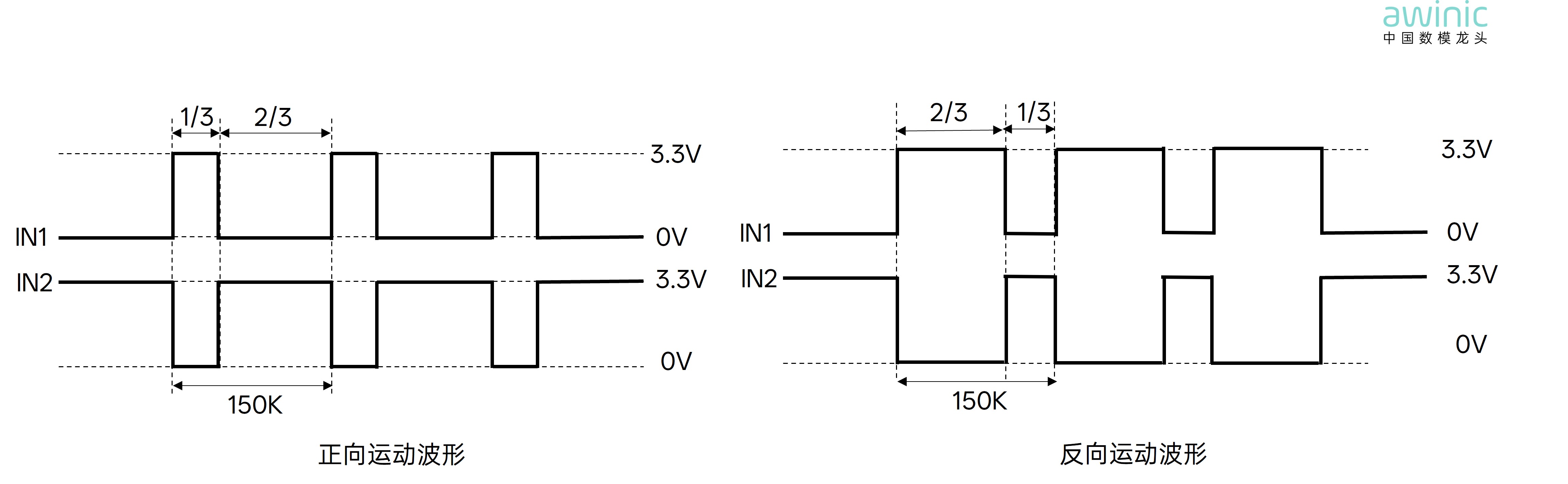
Figure 2 Forward/Reverse motion waveform comparison
From the
figure above, it can be seen that this piezoelectric motor has two input
terminals: IN1 and IN2. The drive parameters for forward and reverse motion are
as follows:
Forward
Motion
The PWM
frequency on both IN1 and IN2 terminals is 150K; the duty cycle of IN1 is
approximately 33.3%, and the duty cycle of IN2 is approximately 66.7%; the
phase of IN1 is set to 0°, and the phase of IN2 is set to 120°.
Reverse
Motion
The PWM
frequency on both IN1 and IN2 terminals is 150K; the duty cycle of IN1 is
approximately 66.7%, and the duty cycle of IN2 is approximately 33.3%; the
phase of IN1 is set to 0°, and the phase of IN2 is set to 180°.
Theoretically,
according to the piezoelectric specifications, after obtaining the motor, PWM
signals should be output to the piezoelectric motor in cycles according to the
forward and reverse waveforms described above. If the period is set to 1
second, the motor will perform open-loop motion cyclically with a 1-second
period.
For
piezoelectric motor applications, awinic works closely with customers to
propose a piezoelectric motor system solution. The system block diagram is as
follows:
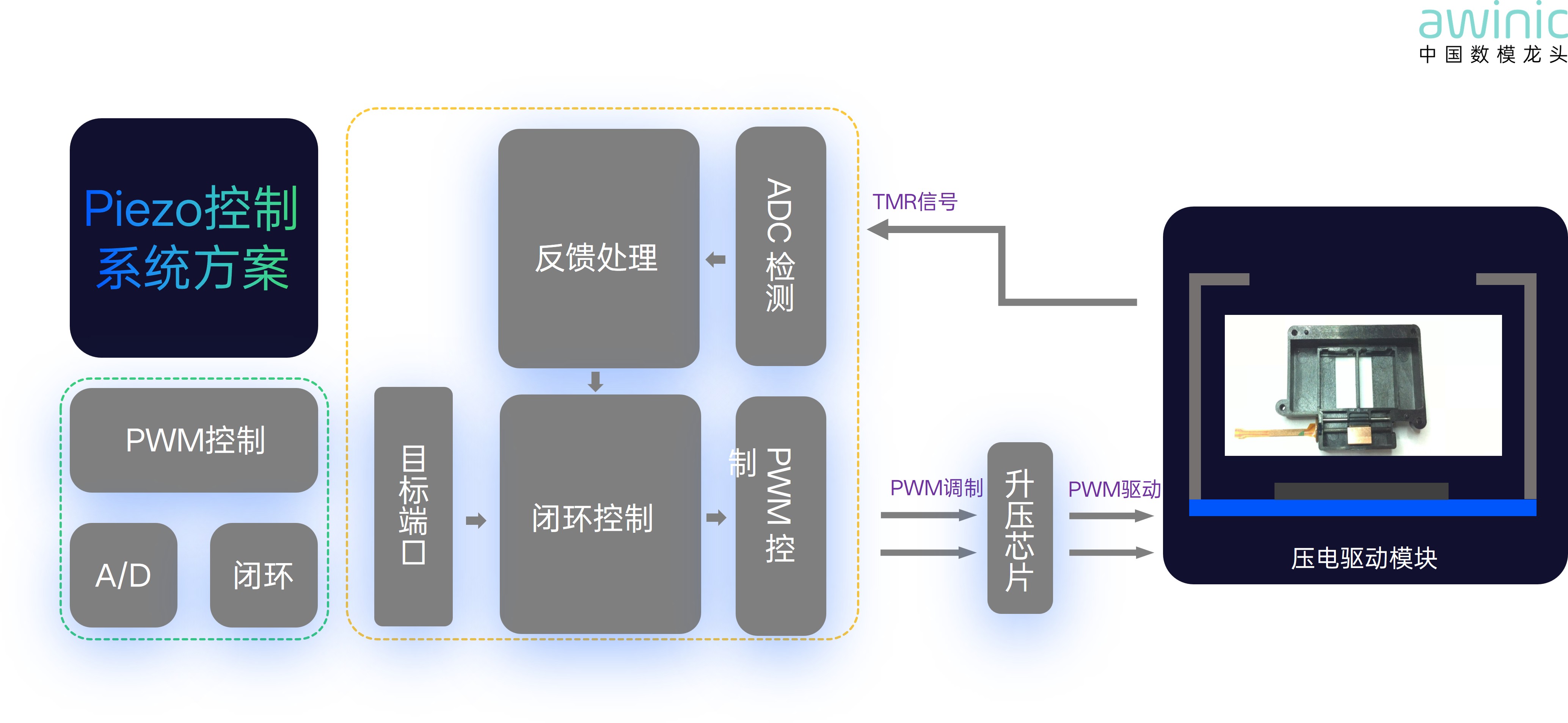
Figure 3 PIEZO control system solution
For hardware
circuit design, please refer to the official awinic website, search in the
Product Center -> Imaging Motion Control -> Optical Image Stabilization
Driver -> AW86102, and consult the technical documentation and product
design guidelines. After connecting the piezoelectric motor load according to
the hardware design, the firmware can be designed to drive the motor in
open-loop motion based on the characteristics of the AW86102 chip. In the
firmware driver, set the corresponding PWM frequency, duty cycle, and phase,
and map the PWM channels to the corresponding OUT drive pins. At this point,
the piezoelectric motor can achieve forward or reverse motion. The hardware
design reference is as follows:
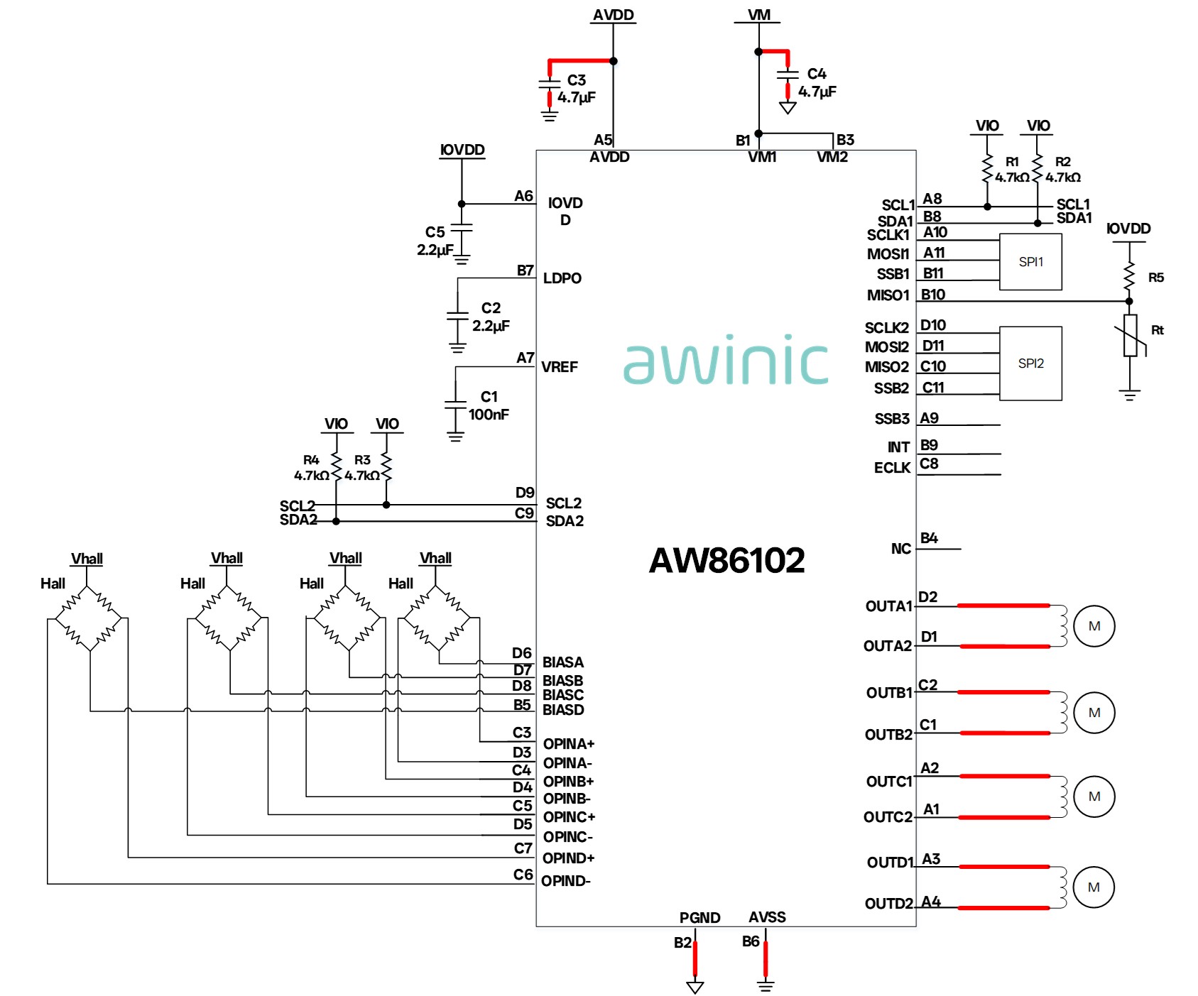
Figure 4 AW86102 application circuit
During the
operation of the piezoelectric motor, because the driver chip outputs
high-frequency square waves, the high-frequency current generates
electromagnetic vibrations on the coils and capacitors, producing subtle
current whining noises. Additionally, sudden voltage changes can intensify
voltage fluctuations and amplify noise. To address the noise issues during
piezoelectric motor driving, awinic provides excellent algorithms and control
schemes that can significantly reduce the noise generated at the piezoelectric
terminals during motor operation.
Noise
Suppression for Piezoelectric Motors
Audio noise
is mainly divided into two types: one is Audio noise generated by motor motion,
whose frequency points generally correspond to positions with larger FRA gain;
the second is Audio noise generated by current, whose frequency generally
corresponds to the loop control frequency Fs. For motor motion Audio noise,
filters can be used to limit the gain at the audio noise frequency points,
reducing the motor motion amplitude at those frequencies and lowering Audio
noise. For current Audio noise, the loop control frequency Fs can be increased
to above 20kHz to avoid the frequency range audible to the human ear, thereby
reducing Audio noise. For most chips, increasing Fs means increased circuit
noise. To avoid this issue, the driver drive frequency can be increased while
keeping the loop Fs unchanged, without increasing circuit noise. For noisy
signals, AW's noise reduction solution employs a composite filter denoising
algorithm:
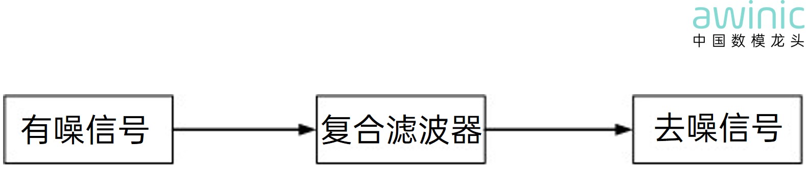
Figure 5
Composite filter
The composite
filter can effectively suppress high-frequency noise such as motor motion noise
and control signal noise. Compared with conventional low-pass filters, it
offers better amplitude-frequency characteristics and reduces the impact on the
phase of low-frequency signals in the control system.
In addition,
in terms of control strategy, awinic also provides an advanced piezoelectric
control drive mode that can resolve the sharp abnormal noise generated by the
driven motor due to frequent PWM phase switching. The following shows a
comparison of audio frequency spectra before and after step response of a
certain AF motor. It can be seen that the overall gain is reduced by more than
10dB, and near 10kHz, the gain drops by more than 20dB, effectively suppressing
high-frequency noise.
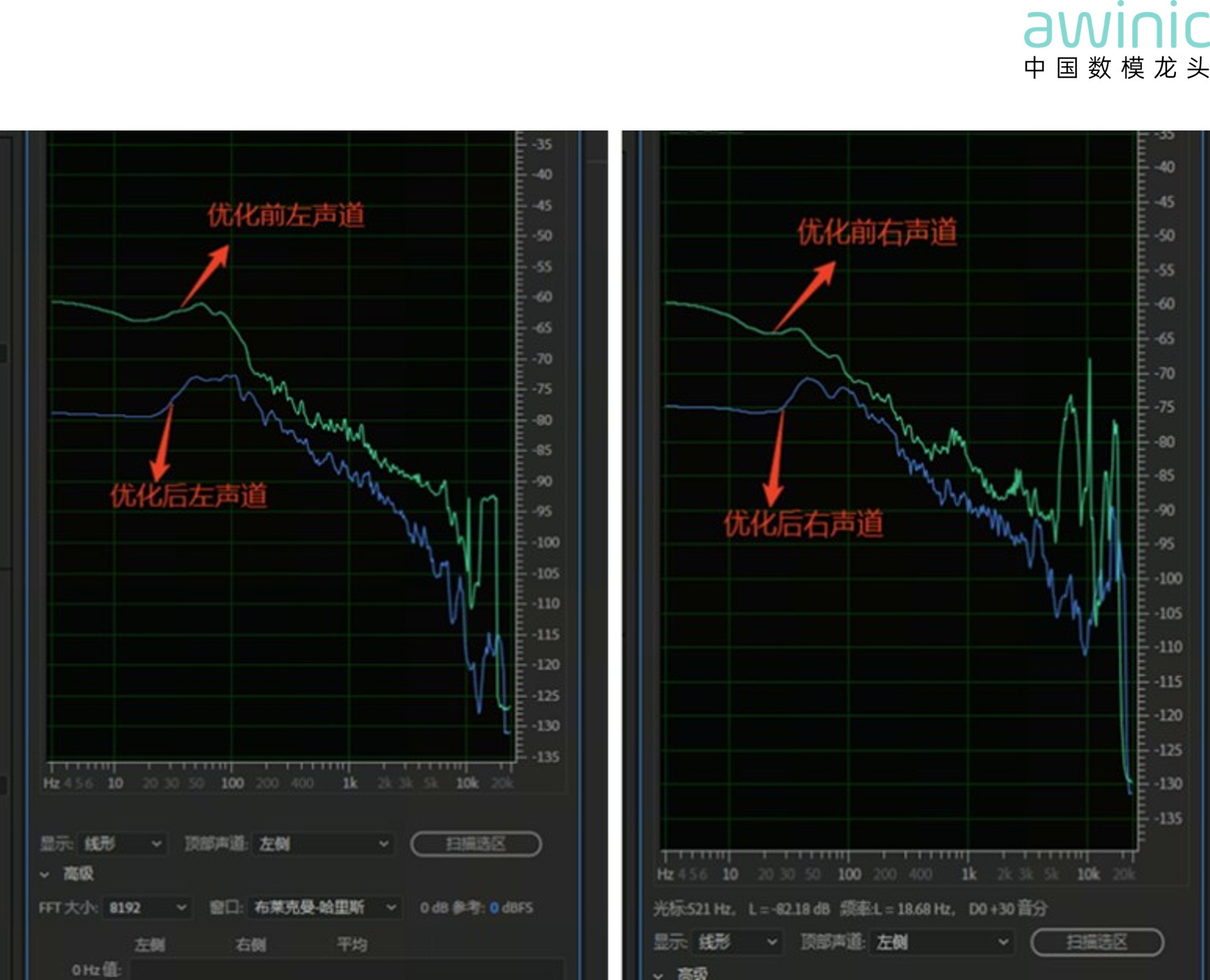
Figure 6
Comparison of left and right channels before and after abnormal noise
optimization
At the same
time, for autofocus and optical image stabilization applications, awinic
continues to launch multiple products, covering open-loop/closed-loop focus
drivers, OIS drivers, piezoelectric drivers, etc., achieving comprehensive
coverage in the VCM motor driver field. This rich product portfolio provides
customers with more options. awinic has been deeply engaged in the VCM product
line for 10 years and is a fully domestically-manufactured producer with
mass-production capabilities across open-loop, closed-loop, and OIS
(integrated, discrete, and SMA) product lines. It has already achieved mass
production with multiple brand customers, including vivo, Lenovo, Asus, OPPO,
etc. At the same time, awinic maintains close cooperation and collaboration
with motor and module manufacturers, offering a complete VCM driver total
solution.
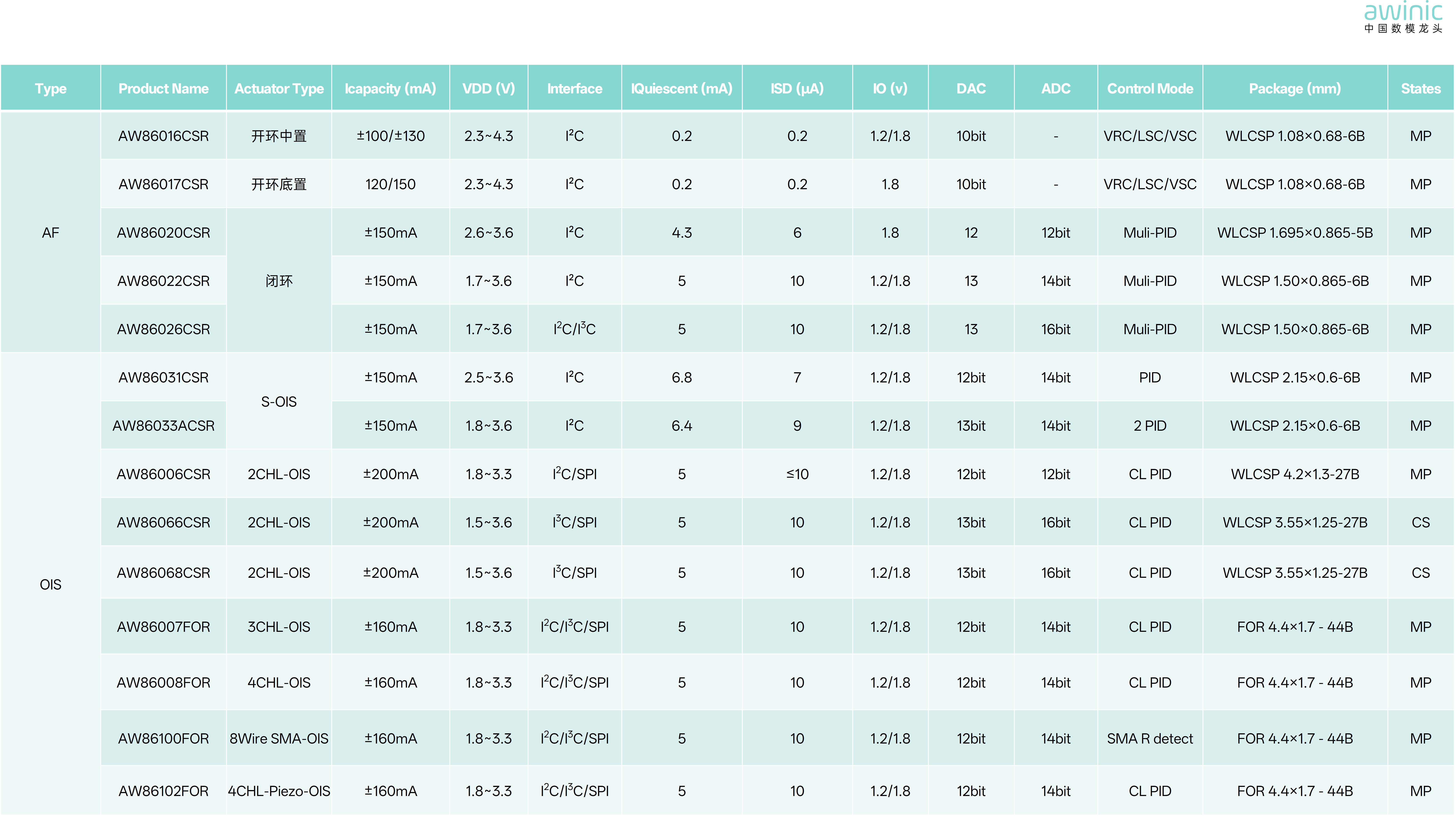
Table 2 Complete VCM driver total solution table