With the widespread
adoption of smart devices, Global Navigation Satellite Systems (GNSS) have
become an "essential feature" for various terminals. The realization
of high-precision positioning relies on a core component—the GNSS Low-Noise
Amplifier (LNA). When satellite signals travel from 20,000 kilometers in
space to the ground, their power drops below -130dBm, making them highly
susceptible to being drowned out by system noise, which can lead to positioning
failure. The key role of the GNSS LNA is to overcome this technical bottleneck:
it amplifies weak signals to a level that can be processed by the platform
system while optimizing the system's signal-to-noise ratio. By placing the GNSS
LNA close to the antenna, signal transmission loss and noise interference can
be reduced. As the first-stage device at the receiving end, its noise
characteristics directly determine the positioning accuracy of the entire
device.
Awinic's All-Scenario GNSS LNA Solutions
As a leader in analog
and mixed-signal semiconductors, Awinic has deeply engaged into the GNSS
LNA field, offering products that cover a wide range of scenarios, including
professional high-precision equipment, consumer-grade smart terminals
(smartphones/wearables), industrial applications, and automotive
transportation. Key highlights include:
· Ultra-Low Noise: High-end
models feature a noise figure as low as 0.5dB, significantly improving
positioning accuracy in complex environments.
· Multi-Band Compatibility: Single
devices support L1/L2/L5 multi-band frequencies, simplifying front-end design.
· All-Scenario Adaptation: From
ultra-low power consumption of 1.2mA (for wearables) to automotive-grade
certified models (for in-vehicle scenarios), the solutions cater to diverse
requirements.
Before introducing the
application solutions, let's briefly outline the four key indicators for
evaluating LNA performance.
Noise Figure: The
"Goalkeeper" of Sensitivity
Noise Figure
is a core performance metric for LNA, directly determining
receiver sensitivity. Awinic's GNSS LNAs achieve industry-leading noise figure
performance: the AW15345DNR and AW15045FDR models can reach as low as
0.50dB, effectively enhancing GNSS positioning accuracy and speed.
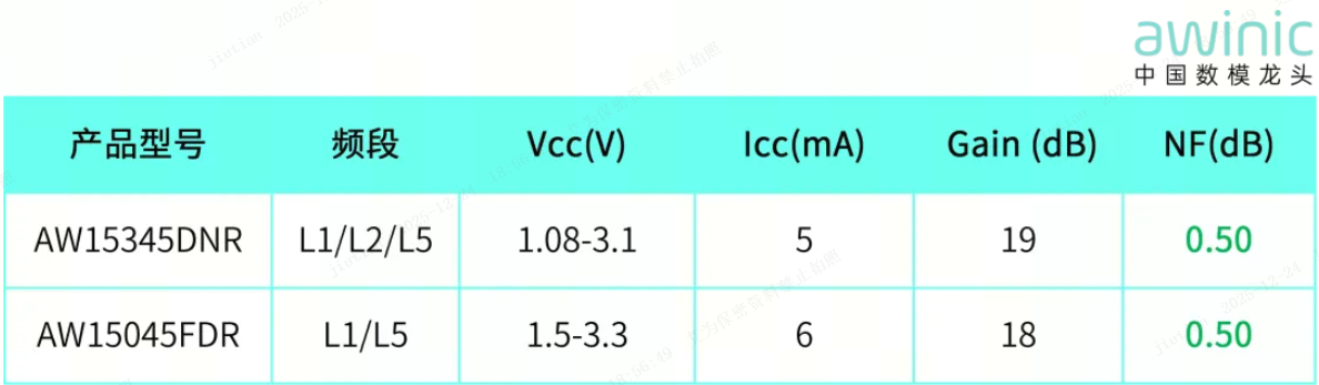
Table 1: Key Specifications of AW15345DNR
and AW15045FDR
Gain: The
"Regulator" of Amplification Capability
The gain parameter
requires careful balancing, as both excessively high and insufficient gain can
affect system performance, depending on the platform's demodulation capability.
Design Considerations:
· Excessively high gain: May cause saturation
in subsequent circuits, leading to nonlinear distortion.
· Insufficient gain: Fails to effectively enhance signal
strength, making it difficult to overcome noise impacts from subsequent
circuits.
To meet the typical
gain requirement of approximately 18dB for eLNA in devices such as smartphones
and wearables, Awinic's GNSS LNA provide precise gain performance. If higher
gain is needed for specific scenarios, it can be achieved by cascading GNSS LNA.
Linearity: The
"Firewall" Against Interference
Linearity
specifications primarily include IP3 (Third-Order Intercept Point) and P1dB (1dB
Compression Point), which determine the LNA's ability to resist interference.
Key Parameters:
· IP3 (Third-Order Intercept Point): >
-10dBm, effectively resisting adjacent channel interference.
· P1dB (1dB Compression Point): >
-20dBm, ensuring no saturation under strong signal conditions.
Awinic's
GNSS LNA model AW15745DNR achieves industry-leading linearity performance, with
a P1dB of -2.5dBm and an IIP3 of up to 3.3dBm. This exceptional linearity
effectively resolves coexistence issues between cellular and GNSS signals in
smartphones, as well as mutual interference problems in multi-mode navigation
scenarios.
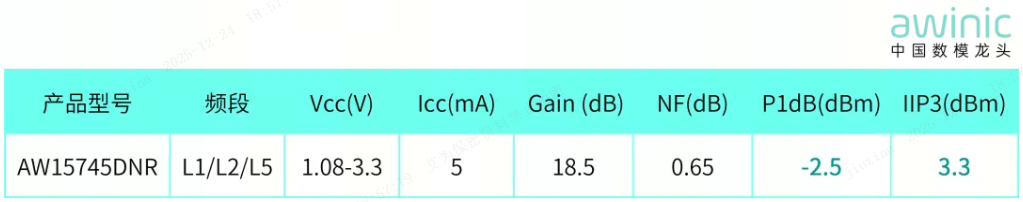
Table 2: Key
Specifications of AW15745DNR
Power
Consumption: The "Meter" of Energy Usage
Awinic has
mass-produced a series of GNSS LNA products with multiple power consumption
levels, comprehensively covering the differentiated needs of various
industries. The core model, AW15085DNR, achieves industry-leading ultra-low
power consumption of 1.2mA, while also offering options such as 2.4mA and
4mA across multiple product tiers.
For wearable
devices, low-power models with power consumption below 4mA are preferred, while
smartphone products can flexibly adapt to models around 6mA.
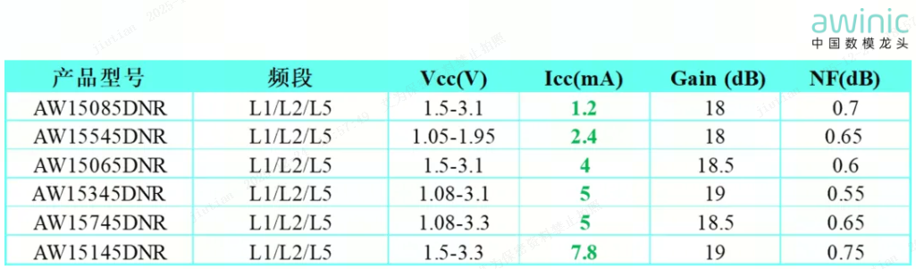
Table 3: Key Specifications
of LNA with Different Power Consumption Levels
Below is a
detailed explanation of typical application solution diagrams across various
fields:
GNSS Circuit
Block Diagram for Smartphones/Children's Watches/Bands
Using Qualcomm & MediaTek Platforms as an Example:
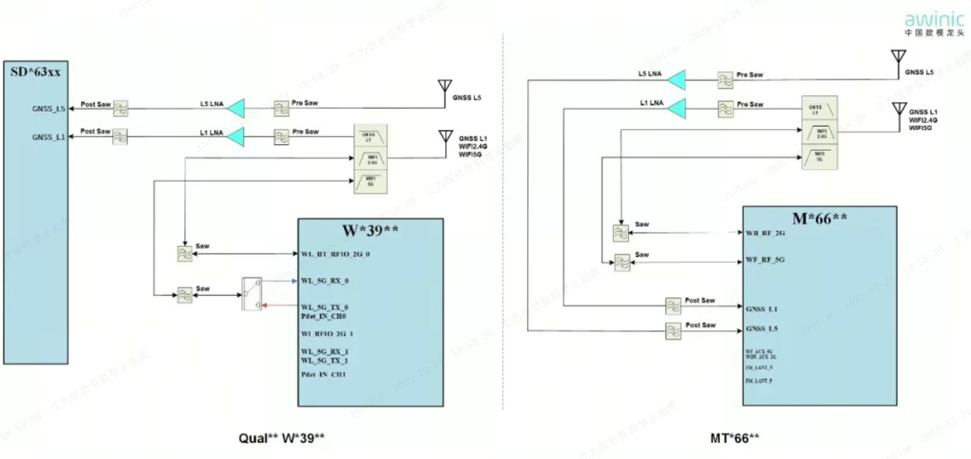
Figure 4: GNSS Circuit Application
Solution Diagram for Smart Terminals
1. Figure 4
shows a typical GNSS circuit application block diagram for smart terminals. Apart from
platform differences, the front-end design for wearables is largely consistent
with that of smartphones. The signal chain is: ANT → Pre SAW → GNSS LNA → Post
SAW → TR. The Post SAW is a compatibility design, typically essential for
Qualcomm platforms. Due to the long trace from the antenna to the RF TR, which
can easily introduce out-of-band interference, it needs to be placed close to
the platform end. For MediaTek platforms, the Post SAW is a compatibility
design and is only used when out-of-band interference exists.
2. Antenna
Design Solutions: The L1 antenna is usually shared with Wi-Fi 2.4G/5G. The L5
antenna can either use an independent solution or be shared with MIMO Wi-Fi
2.4G/5G or the main RF. The specific approach depends on the PCB layout and
antenna environment.
3. B13 Band
Interference Protection: If a smartphone supports B13 (787MHz), consideration must be
given to its second harmonic interfering with GPS. Protection measures include:
·
Ensuring isolation between the B13 second harmonic and the GPS
antenna.
·
Selecting a Pre-SAW filter with high out-of-band rejection.
·
Reserving an LC circuit at the B13-PA output for second harmonic
attenuation.
·
Reserving an LC circuit after the GPS antenna for harmonic
attenuation. The recommended circuit is shown in Figure 5
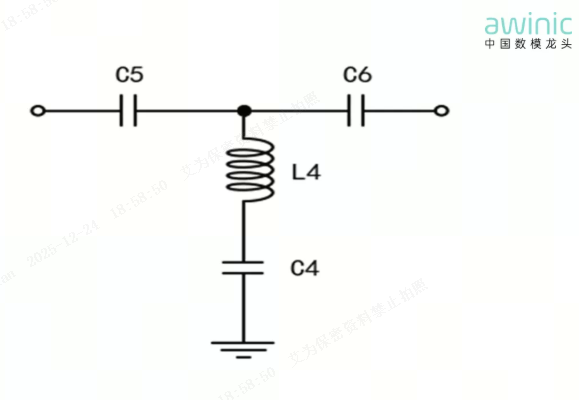
Figure5: 787MHz
Notch Filter
Low Insertion Loss Notch Network
Recommended BOM: L4:15nH, C4:2.7pF, C5:7.5pF, C6:7.5pF
The insertion loss of this network is approximately
0.2dB, with a rejection level of about 10dB at 787MHz.
We recommend placing this HPF (High-Pass Filter) at the
input of the Pre-SAW filter.
Therefore, this network does not require additional
matching components; only fine-tuning of C5/C6 based on actual conditions is
needed.
GNSS Module
Circuit Application Block Diagram
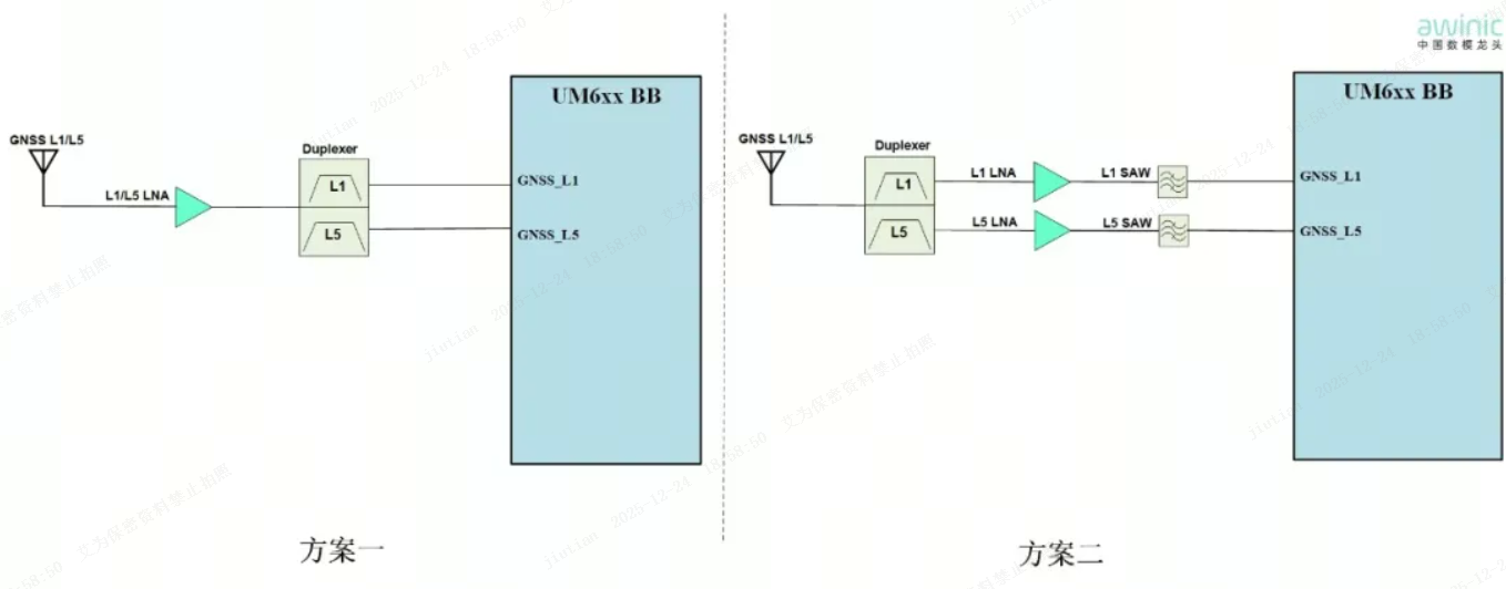
Figure 6: GNSS Module Circuit Application
Solution Diagram
1. Single LNA Shared Matching Solution: One GNSS LNA
simultaneously amplifies L1+L5 signals. The filter in the second stage has poor
anti-interference capability, making it suitable for medium-to-low precision
positioning scenarios such as shared bicycles, electric vehicles, and logistics
tracking.
2. Dual LNA Dual SAW Solution: Two GNSS LNAs are
paired with front-end and back-end SAW filters, making it suitable for complex
electromagnetic environments such as drones, autonomous vehicles, and automatic
lawnmowers.
GNSS Active
Antenna Circuit Application Solutions
The following three design solutions are recommended:
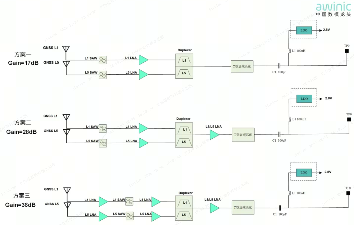
Figure 7: GNSS Active Antenna Circuit
Application Solution Diagram
1. GNSS Active
Antenna Design: The antenna gain requirements should be determined based on the
differences in GNSS module platforms. Common specifications are 17dB, 28dB, and
36dB. To meet these varying gain requirements, the three recommended
application solutions above are provided. The positioning of the cascaded LNAs
(front or rear) can be adjusted based on actual conditions.
2. Key Points
for Front-End Circuit Design: The selection of the first-stage
component after the antenna should consider the antenna type. For multi-band
integrated antennas (GNSS integrated with Cellular/WiFi), it is recommended to
prioritize placing a filter in series to suppress performance degradation
caused by out-of-band interference. For external GNSS antennas, due to less
out-of-band interference, placing the GNSS LNA first can significantly enhance
GNSS signal performance. The LDO in the circuit provides a compatible design
for high-voltage platform power supply, delivering the appropriate voltage to
the GNSS LNA. Additionally, TP0 is the feed point for connecting the GNSS
module, where C1 (100pF) serves to block DC and pass high-frequency signals,
while L1 (100nH) functions to block high-frequency signals and pass DC.
3. LNA
Selection Recommendations: The first-stage LNA after the antenna can be selected based on
requirements, while the final stage should use an L1/L5 combo LNA. Awinic's
AW15745DNR requires only one input inductor to achieve simultaneous
amplification of dual-band signals. Furthermore, the AWR5005DNR-Q1 has passed
the AEC-Q100 automotive certification, offering customers greater flexibility
in design and selection.
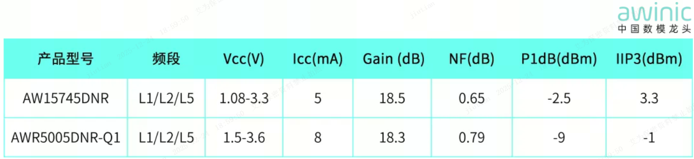
Table 8: Key
Specifications of AW15745DNR & AWR5005DNR-Q1
As the core
component determining positioning system performance, the GNSS LNA directly
defines the level of positioning accuracy in emerging fields such as autonomous
driving and the Internet of Things. Facing continuously rising demands for high
performance, scientific selection and optimized design are key to achieving
precise positioning. As a leader in analog and mixed-signal semiconductors,
Awinic remains committed to technology as its core, deeply engaged and
iterating to empower all-scenario applications with even better products. Below
is the selection guide for Awinic's full range of GNSS LNA products. Stay tuned
for subsequent new products!
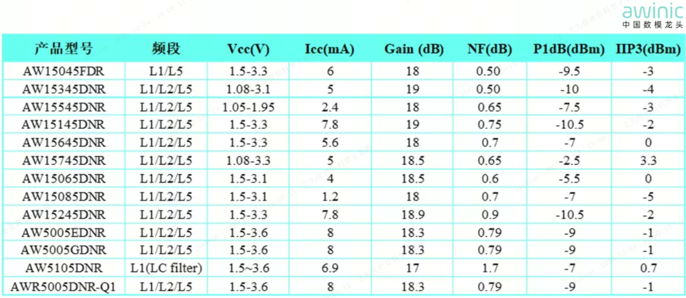
Table
9: GNSS LNA Selection Guide


