[Technical Post] All-Scenario Automotive Rhythmic Lighting Solutions
01. Introduction
In recent years, ambient lighting has almost become a standard feature in smart cockpits. From a single ambient light on the door handle to hundreds of light strips in the entire vehicle cockpit, the application of ambient lighting has become increasingly widespread. More and more manufacturers and users are paying attention to ambient light driver technology, and market demand continues to rise. Against this backdrop, Awinic has launched an ambient lighting solution consisting of AW32F010QNR-Q1 and AW21036QPY-Q1.
Figure 1: Smart Cockpit Lighting Effect Diagram
02. Music-Synchronized Lighting Solution
— Making the Smart Cockpit “Visibly Intelligent”
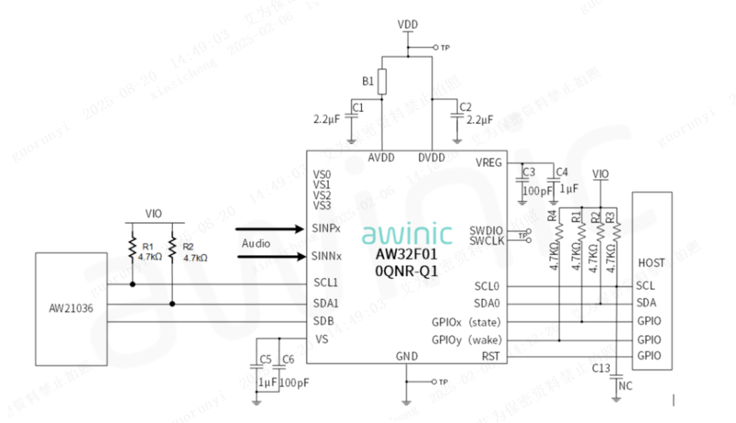
Ordinary dynamic effects can barely meet market demands anymore. The AW32F010QNR-Q1 supports audio signal collection, and when combined with the high-precision ADC (Analog-to-Digital Converter) and the excellent current control capability of the AW21036QPY-Q1, the two chips work together to deliver more rhythmic and delicate lighting effects, better demonstrating the intelligence of the smart cockpit. Below is an explanation of how this design is implemented.
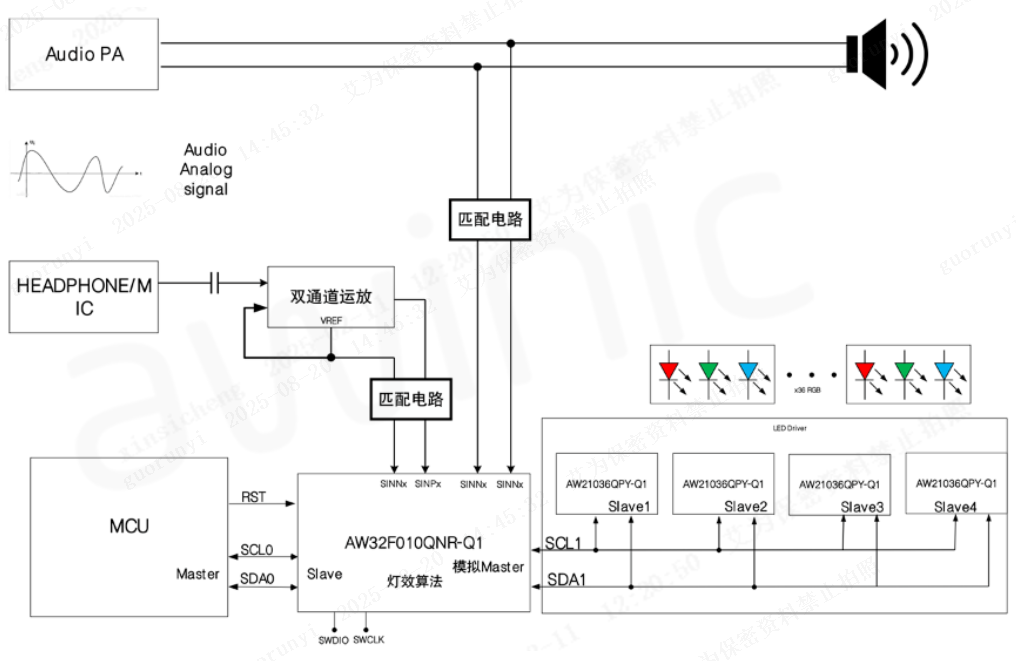
The AW32F010QNR-Q1 supports multi-channel differential signal input, providing a rich range of sound pickup solutions and strong compatibility with systems and platforms. As shown in Figure 2, the AW32F010QNR-Q1 is compatible with PA (Power Amplifier) differential output, MIC (Microphone) output, and HEADPHONE output simultaneously. Additionally, only one I2C bus is required to connect 4 AW21036QPY-Q1 chips, enabling control of up to 144 LED channels.
Furthermore, the AW32F010QNR-Q1 supports in-system programming (ISP) of external control chips. Users can perform online upgrades via I2C, allowing for anytime, anywhere updates to lighting effects.
Figure 2: Reference Design of AW32F010QNR-Q1 + AW21036QPY-Q1
Sound Pickup from In-Vehicle Speakers
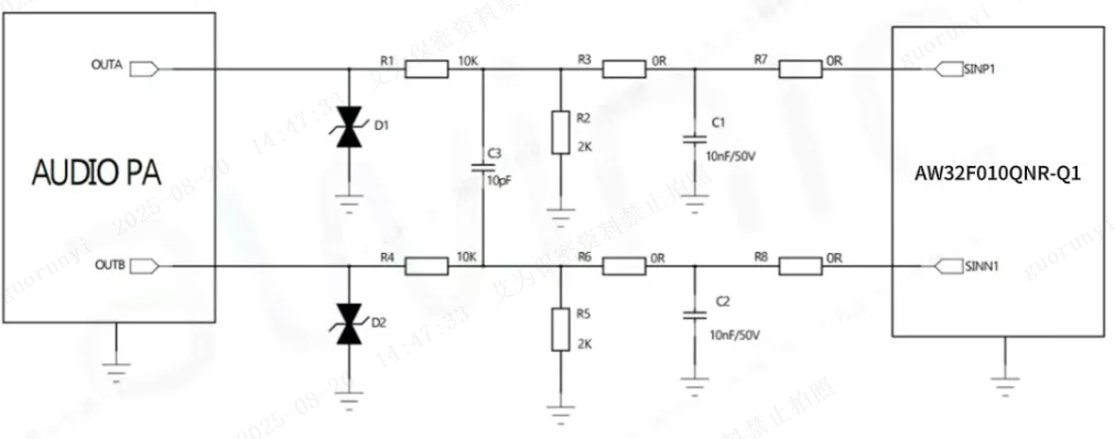
Media playback has become a standard feature in automobiles, and speakers are essential electronic components for this function. The AW32F010QNR-Q1 can collect output signals from Class D or Class AB audio amplifiers, which are then connected directly to the SINNx/SINNPx pins of the AW32F010QNR-Q1 via a resistor divider and RC filter.
Figure 3 provides a reference design for sound pickup from a single-ended DC-biased differential output signal. The recommended input signal amplitude for the SINP/SINN pins of the AW32F010QNR-Q1 is 2V. Therefore, it is first necessary to confirm the maximum voltage of the PA at full volume, then use a resistor divider to reduce the voltage to the recommended range before connecting it to the AW32F010QNR-Q1. In Figure 3, the PA output is +10V. For OUTA, R1 is set to 10KΩ and R2 to 2KΩ, resulting in a divided voltage of approximately 2V, which meets the design requirements. Similarly, R4 and R5 for OUTB are set to 10KΩ and 2KΩ, respectively.
The cutoff frequency of the RC filter is calculated as f = 1 / (2 × π × (R1//R2) × C1). For dynamic visual appeal, the low-pass cutoff frequency can be set to approximately 10kHz, which does not require processing the entire frequency range audible to the human ear. The low-pass cutoff frequency in the figure is approximately 10kHz.
Figure 3: Reference Schematic for Sound Pickup from PA Output
Sound Pickup from In-Vehicle MIC
With the rapid development of the live-streaming industry, the number of live-streaming and short-video users has grown significantly, and people increasingly expect to record videos anytime, anywhere. Considering that many car owners want to use music-synchronized lighting effects when recording short videos or live-streaming singing in their cars, the AW32F010QNR-Q1 + AW21036QPY-Q1 solution also supports sound pickup from microphones. No wired connection to the audio source is required—only a MIC installed in the car is needed to enable this stunning feature.
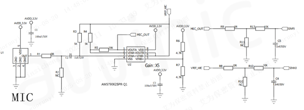
The MIC output is a single-ended DC-biased signal. This signal is sent to the op-amp (operational amplifier) via a DC-blocking capacitor, then passed through a resistor divider and RC filter before being fed to the SINNx/SINPx pins of the AW32F010QNR-Q1.
Figure 4 provides a reference design: first, the MIC signal is processed by an op-amp (AWS79062SPR-Q1), and the op-amp’s output (OUT) and Vref voltage are then sent to the AW32F010QNR-Q1 via a voltage divider and filter circuit. As shown in Figure 4, R1/R2 are reserved as MIC voltage divider resistors. Typically, the MIC output voltage is low, so it can be directly connected to the op-amp via a DC-blocking capacitor according to the actual design. The output voltage range of the op-amp is then controlled based on its reference configuration. For example, in Figure 4, R3, R4, and R5 form the feedback network of the op-amp circuit, where the amplification factor β = (R5 + R4) / R4. R6 and R7 are voltage divider resistors for Vref, which is usually set to half of AVDD. The circuit design after the op-amp can directly reference the single-ended DC-biased differential output circuit described in the previous section.
Figure 4: Reference Circuit for MIC Sound Pickup
Sound Pickup from In-Vehicle Headphone Jack
Some car owners or passengers may want to play audio from mobile devices in the car. Can the solution still support music-synchronized lighting when users connect an external audio source via the headphone jack? The answer is yes. To enhance compatibility, the AW32F010QNR-Q1 also supports sound pickup from the headphone output of a Codec.
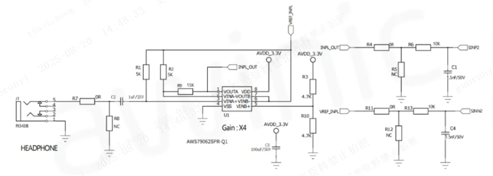
The HEADPHONE output is typically a positive/negative single-ended DC-biased signal, similar to the MIC output. It can be sent to a dual-channel op-amp (AWS79062SPR-Q1) via a DC-blocking capacitor, then connected to the SINNx/SINPx pins of the AW32F010QNR-Q1 through a resistor divider and RC filter.
The reference circuit design for the HEADPHONE is highly similar to that of the MIC (described in the previous section). As shown in Figure 5, in the op-amp circuit, R1, R2, and R9 form the feedback network. The design of the circuit after the op-amp is similar to that of the single-ended DC-biased differential audio source output.
Figure 5: Reference Circuit for HEADPHONE Sound Pickup
03. Introduction to AW32F010QNR-Q1 and AW21036QPY-Q1
AW32F010QNR-Q1
The AW32F010QNR-Q1 is a professional automotive-grade music rhythmic SoC (System on Chip) chip. It features a 24MHz 32-bit core, can multiplex up to 16 GPIO pins, and supports ISP (In-System Programming) and ICP (In-Circuit Programming) functions. It also provides multiple 100K SPS 14-bit SAR ADCs. Additional features include:
-
AECQ-100 Grade 2 qualification (operating temperature range: -40~105℃)
-
24MHz 32-bit MCU
-
CRC32 and high-speed divider
-
Support for In-System Programming (ISP) and In-Circuit Programming (ICP)
-
2 watchdog timers
-
Support for 1MHz I2C
-
UART support
-
16 GPIO pins
-
Power-on reset, low-voltage detection
-
Low-voltage reset and temperature detection
Figure 6: Reference Design of AW32F010QNR-Q1
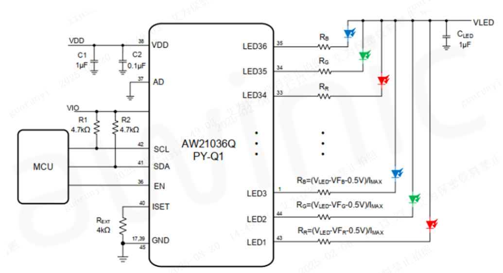
AW21036QPY-Q1
The AW21036QPY-Q1 is a professional ambient light driver chip. It supports a maximum driving current of 50mA and provides 36 constant current source channels. It also supports 256-level global current adjustment, and each channel can independently control DC current and PWM current, enabling extremely delicate breathing light effects. Additional features include:
-
AECQ-100 qualification
-
High-precision current sources
-
EMI and audible noise suppression
-
Flexible lighting effect pattern control
-
Open/short circuit detection
-
Automatic power reduction function
-
Over-temperature protection
Figure 7: Reference Design Diagram of AW21036QPY-Q1
04. Introduction to Awinic Breathing Light Driver Products
To meet the needs of different customers and products in the market, Awinic has launched a series of breathing light driver products, including direct-drive and matrix-type options, with multiple models and packages available for selection.

Table 1: Product Model and Package Reference
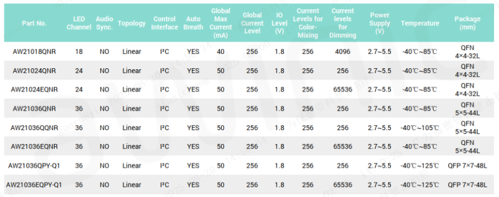
Table 2: Product Model and Package Reference
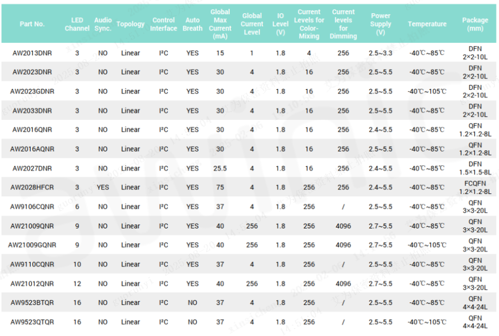
Table 3: Product Model and Package Reference