In modern electronic devices, the USB Type-C interface has become the most widely used standard due to its high bandwidth, high power capabilities, and support for reversible insertion. However, as devices tend to be more miniaturized, with higher charging power and diversified functions, interface reliability faces more severe challenges. Especially in daily life, Type-C ports are often exposed to humid or high-temperature environments—moisture or domestic water seeping into the interface may cause a series of problems, ranging from unstable charging and device short circuits to even permanent device damage. How to effectively detect and prevent moisture intrusion has become a key issue in improving the reliability of USB Type-C interfaces. This article will explore moisture detection technologies for USB Type-C interfaces, analyzing their working principles, implementation methods, and corresponding products from Awinic.
To address this challenge, the USB Type-C 2.4 protocol introduces the concept of LPD (Liquid Presence Detection), which aims to ensure the stability and safety of electrical devices by detecting and protecting against additional parasitic leakage paths in the interface. There are generally several implementation approaches:
1. Voltage/Current Monitoring
Between the power pins and ground of the interface, as well as between data transmission lines, the LPD system continuously monitors changes in voltage and current. Abnormal current flow or voltage deviations may indicate the presence of an equivalent leakage path caused by moisture intrusion.
2. Impedance & Capacitance Analysis
In addition to voltage and current monitoring, LPD technology can also determine the electrical state of the interface through impedance analysis. Moisture seeping into the interior of the interface may cause changes in the impedance or capacitance of certain electrical paths, and LPD can detect such changes through precise impedance measurement.
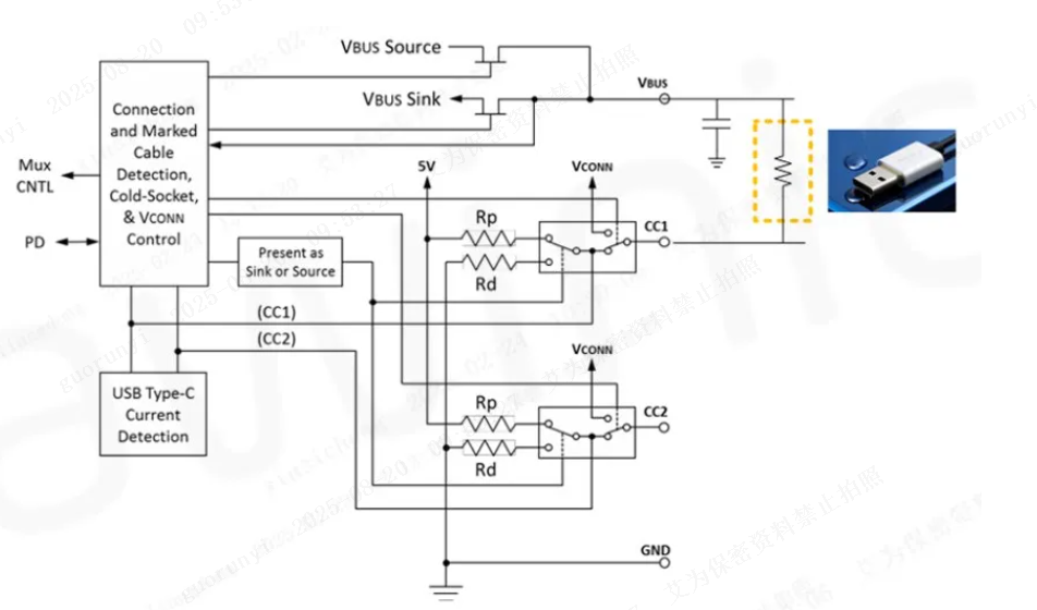
The figure below shows a typical equivalent circuit diagram of moisture intrusion:
Figure 1: Equivalent Schematic Diagram of Type-C Port Moisture Intrusion
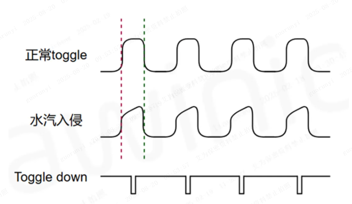
The corresponding VBUS and CC pin waveforms are as follows:
Figure 2: Measured Waveform Diagram of Type-C Port Moisture Intrusion
LPD Mechanism Design Based on Waveform Analysis
-
When the CC (Configuration Channel) is in the toggle state, the CC pin level continuously switches between 0 and VDD voltage. If moisture exists in the CC path, it will cause a micro-short circuit. At this time, the internal resistance of the CC, the micro-short circuit resistance, and the capacitor on the VBUS form an RC low-pass filter, which filters out the high-frequency components of the CC’s rising and falling edges, resulting in a slower change in the CC terminal waveform.
-
During the non-active level inversion process, if the voltage is at an intermediate potential, it will trigger a CC toggle interrupt.
-
Based on this, a timer can be used to record whether a toggle interrupt occurs within a unit time interval (e.g., 2 seconds). If an interrupt occurs, the counter increments by 1; if not, the counter resets to zero. When the counter reaches 50, a moisture warning is triggered. At this point, the CC terminal is set to a pure SNK (Sink) port, and a moisture event is reported to the AP (Application Processor) side.
-
The AP side can restart the CC port’s DRP (Dual Role Port) function.
This is the LPD detection solution adopted by Awinic’s first-generation PD PHY (Power Delivery Physical Layer) – AW35615CSR. With a cumulative shipment of nearly 100 million units, this chip has entered the official reference design solutions of MTK, Spreadtrum, ASR, and other companies due to its excellent performance.
Building on this foundation, Awinic continues to pursue higher LPD detection accuracy and sensitivity, and has launched a second-generation PD PHY solution with a built-in patented hardware moisture detection circuit. Its principle is explained in conjunction with the following figures:
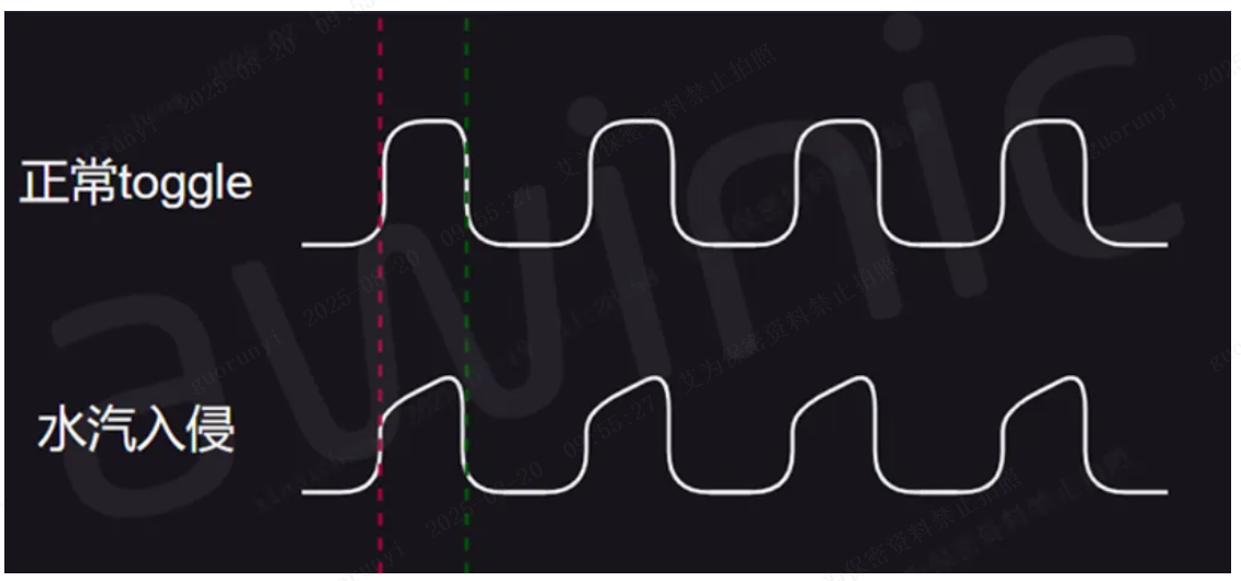
Figure 3: Schematic Diagram of CC PIN Toggle
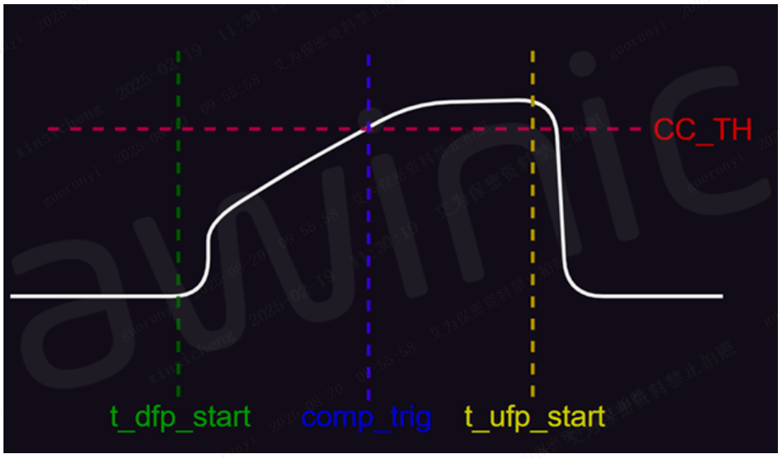
Figure 4: Waveform Analysis Model Diagram of CC Pin After Moisture Intrusion
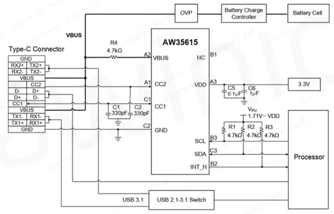
It can be seen that after moisture intrusion, due to the presence of a parasitic low-pass filter, the rising edge of the CC port level becomes abnormally slow. By setting parameters such as the target CC VOL (Voltage Output Low) level and the time required to reach the target level, flexible control over the sensitivity of moisture intrusion detection can be achieved. The typical application diagram of Awinic’s second-generation PD PHY product AW35615PFCR based on this technology is as follows:
Figure 5: Typical Application Block Diagram of AW35615PFCR
Its key parameters are:
-
Supports USB PD 3.1 28V EPR (Extended Power Range)
-
Superior eye diagram performance
-
Maximum withstand voltage of CC pin: 32V
-
Self-developed complete PD protocol stack certified by CTS (Compliance Test Specification)
-
VCONN pin eliminated for more convenient PCB layout
-
Supports 1.2V and 1.8V I2C communication
-
Supports dead battery mode (functions as a SNK when unpowered)
-
Built-in patented LPD hardware algorithm
-
Supports VBUS detection and discharge control functions (avoids VBUS electrochemical corrosion and aging loss)
-
Supports Wake low-power detection mode
It is believed that through the detailed explanation of LPD technology above, you have gained a deeper understanding of its working principle, implementation method, and important role in ensuring device stability. With its profound technical accumulation in related fields, Awinic has carefully prepared a series of rich and professional port protection and protocol solutions, which can fully meet the diversified adaptation needs in different application scenarios. If you wish to learn more, please feel free to contact us via phone at any time.