From interpupillary distance adjustment to game controllers and magnetic-axis keyboards, more and more human-machine interaction devices are transitioning from“trigger detection”to“continuous sensing of position, travel, and force”high-life, low-wear, sealablestructural designs.
Starting with the Hall Effect
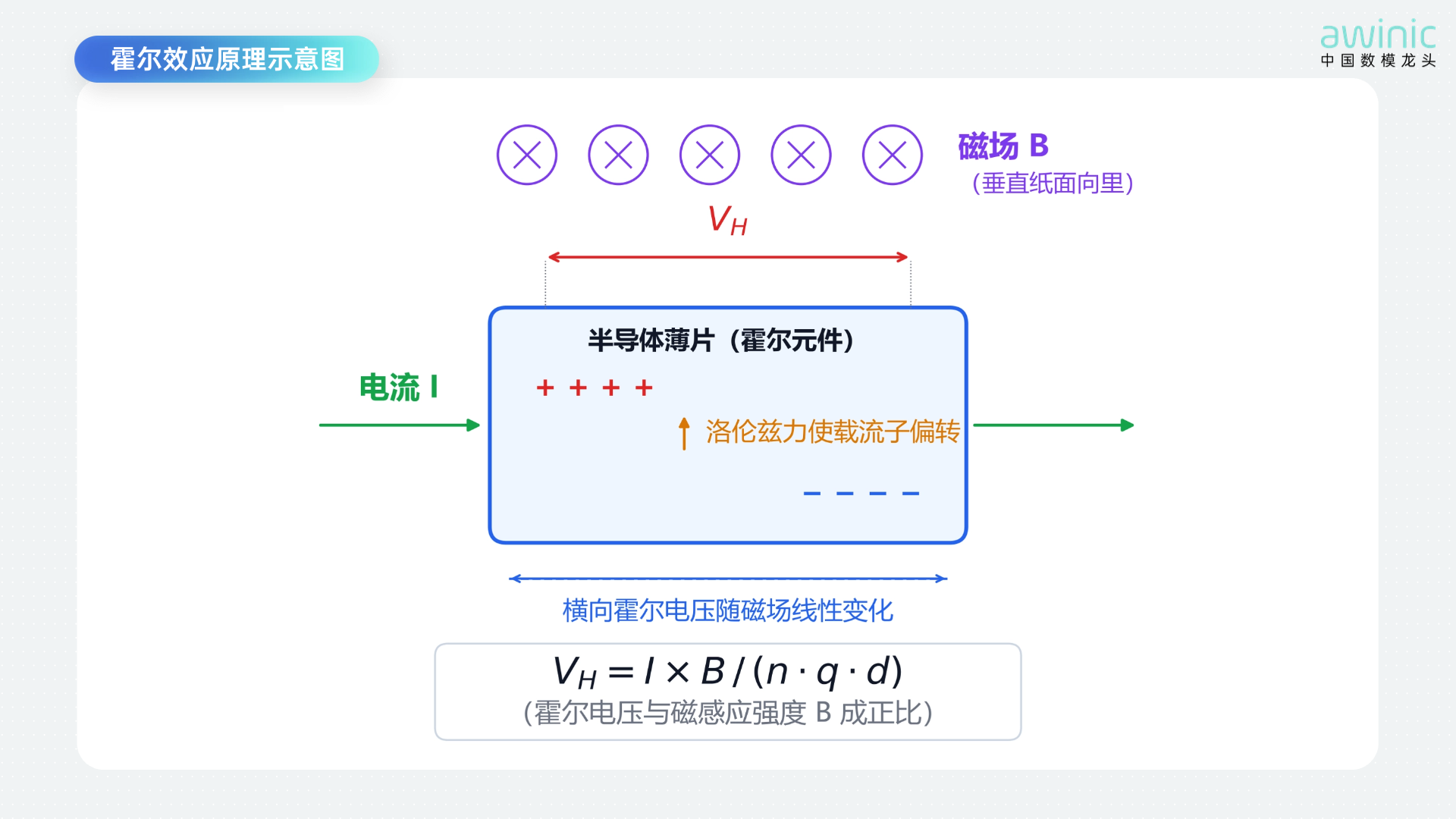
All characteristics of linear Hall sensors can be traced back to the Hall effect. Understanding its physical process helps us perform more accurate magnetic circuit design, sensitivity selection, and error analysis., The Hall effect (Hall Effect) was discovered by the American physicist Edwin Hall in 1879 : When current I flows through a semiconductor wafer, if a magnetic field Bis applied perpendicular to the direction of the current, charge carriers (electrons or holes) are deflected and accumulate on one side of the wafer due to the Lorentz force, forming a transverse voltage perpendicular to both the current and the magnetic field,——known as the Hall voltage VH
Figure1 Schematic diagram of the Hall effect principle
Current flows horizontally, the magnetic field passes vertically through the chip surface, and the Lorentz force deflects charge carriers to one side, forming a transverse Hall voltage.
The quantitative relationship is:VH = (I × B) / (n × q × d)
where n is the carrier concentration,q is the electron charge, andd is the wafer thickness. Once the chip process is determined,VH is proportional to IandB ——This is the physical origin of“linearity”: whatever multiple the magnetic induction intensity B changes by, the Hall voltage changes by the same multiple.
Key conclusions:
•Sensitivity is determined by material and thickness: the lower the carrier concentration (such as in Gallium Arsenide GaAsor Indium Antimonide InSb) and the thinner the wafer, the higher the sensitivity;although Silicon-based Hall elements have slightly lower sensitivity, their mature process, low cost, and ease of monolithic integration with signal processing circuits make them the mainstream choice for magnetic chip design.
•Linear Hall = Hall Element + Signal conditioning circuit: The output of a bare Hall element is only at the millivolt level; it must be paired with amplification, offset cancellation, temperature compensation, and other circuits to become a usable chip.
Why are linear Hall sensors suitable for position and travel detection?
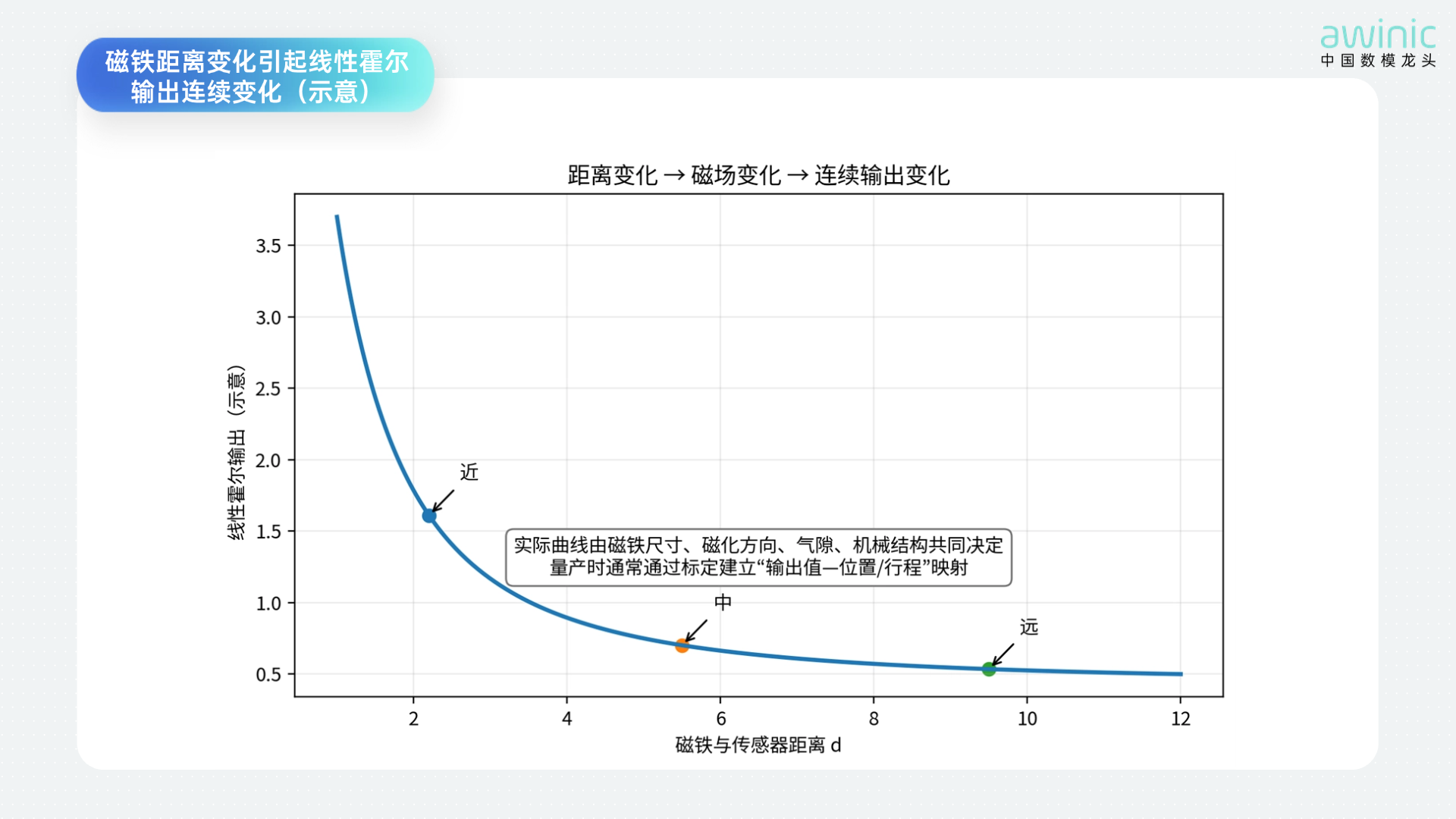
In position detection scenarios, what is actually measured is usually not the“distance”itself, but rather the“change in magnetic field caused by position changes”distance, travel, angle, gear position, or even pressing force through calibration.
Figure 2 Changes in magnet distance cause continuous changes in linear Hall output (schematic)
It should be noted that the relationship between magnetic field and distance is not inherently linear. Magnet size, material, magnetization direction, air gap, sensor sensitivity, and mechanical tolerances all affect the curve. Therefore, a more common engineering practice is: first ensure monotonicity and resolvability within the target operating range, then convert the Hall output to the true position via segmented calibration, look-up tables, or fitting.
AnalogWorking Principles of Analog Linear Hall and Digital Linear Hall Sensors
Figure 3 Signal Chain Comparison of Two Types of Linear Hall Sensors
Analog Linear Hall: Converting Magnetic Field Strength into a Continuous Analog Voltage
Analog linear Hall chips typically amplify the weak signal generated by the Hall element through an on-chip analog front-end, perform offset cancellation and temperature compensation, and finally output a continuously varying analog voltage from the VOUT pin. For common bipolar linear output devices, the output near zero magnetic field is often located near the midpoint of the power supply;N/S changes in polarity cause the output to shift towards higher or lower voltages. Unipolar solutions can optimize the effective dynamic range for a single magnetic field direction.
The system side usually uses an MCU ADC to acquire this voltage, followed by filtering, calibration, and position conversion. Its advantages includesimple interface, direct response chain, and easily controllable output bandwidth; however, in large-scale multi-channel applications, considerations must be given to ADC channel count, multiplexing, analog trace noise, reference voltage stability, and per-channel consistency.
Digital Linear Hall: On-chip Completion of ADC and Digital Processing
A digital linear Hall sensor is not“merely a 0/1 output”digital switch Hall sensor. It still senses continuous magnetic field strength, but integrates the analog front-end,ADC, digital calibration/filtering, and other stages inside the chip, ultimately transmitting magnetic field information to the main controller in the form ofdigital codes.
This architecture can reduce the system's reliance on MCU ADC resources and high-impedance analog traces, and facilitatescompleting gain, zero-point, temperature drift, and consistency calibration internally within the chip. Depending on the product definition, the digital interface may adopt I²C,SPI, single-wire/dedicated serial interfaces, or support multi-device daisy-chain/data transmission methods.
Typical Application 1:VR/AR Interpupillary Distance Adjustment Detection in Devices
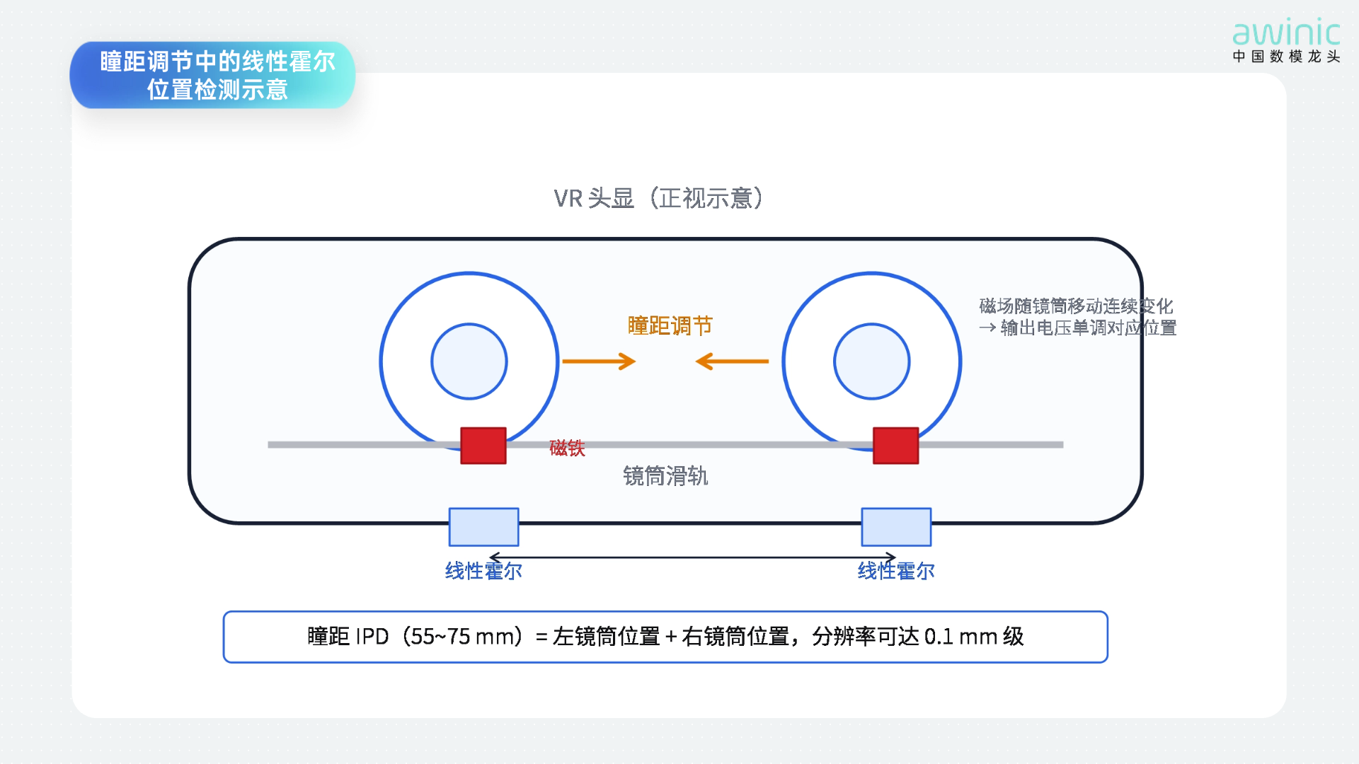
In VR/AR head-mounted displays, interpupillary distance (IPD) adjustment requires moving the left and right lens barrels or optical components to positions matching the user's eyes. Traditional mechanical potentiometers can directly measure position but suffer from issues such ascontact wear, lifespan, and structural sealing. Adopting a non-contact solution using“magnets + and linear Hall sensors”can convert the displacement of the slider or lens barrel into continuous magnetic field changes.
Figure 4 Schematic of Linear Hall Position Detection in Interpupillary Distance Adjustment
-
The magnet is fixed on the moving part, and the linear Hall sensor is fixed on the housing/PCB; during movement, the output changes continuously
-
The main controller converts the output value into the left/and right lens barrel positions and the final interpupillary distance through one-point or multi-point calibration
-
In addition to displaying the interpupillary distance value, it can also be used forMotor closed-loop control, soft limit protection, factory calibration, and abnormal jam detection
-
If the structural space is narrow, the monotonicity and resolution within the operating range can be improved by adjusting magnet polarity, magnetic circuit guidance, and sensor layout.
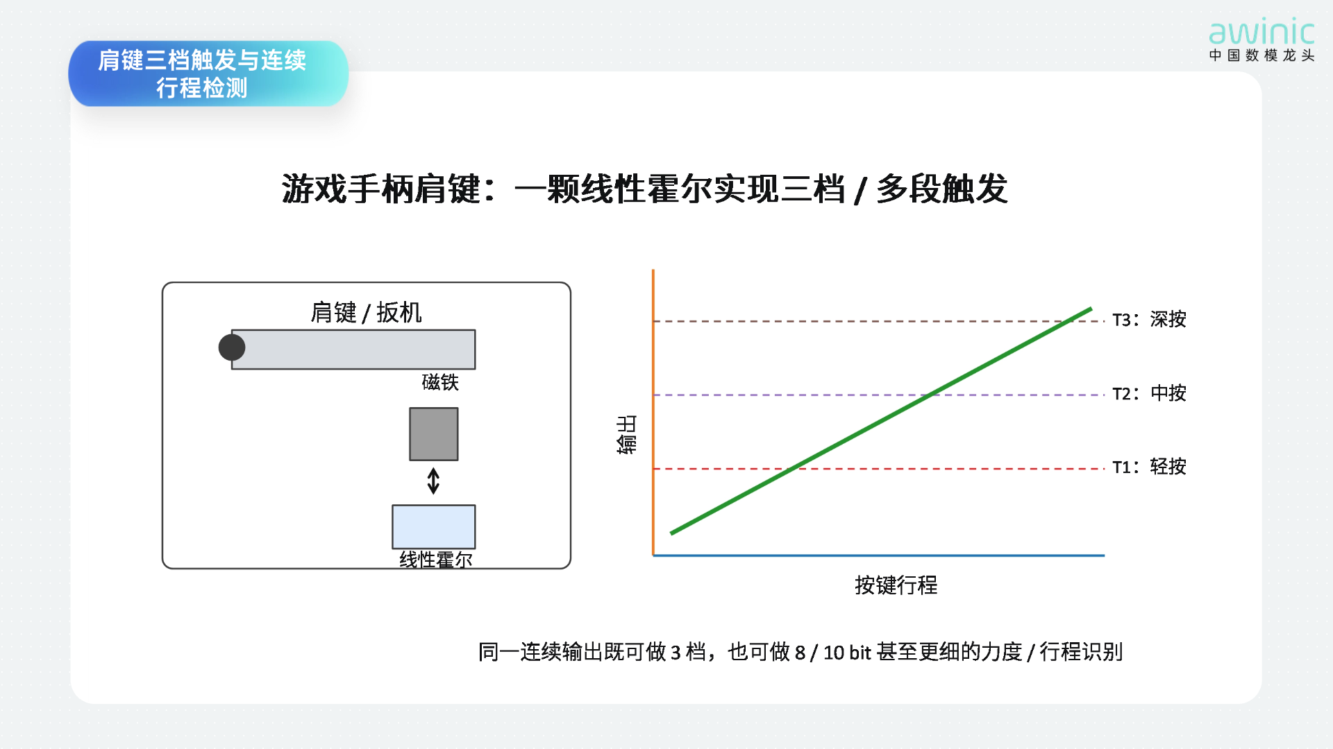
Typical Application 2: Game Controller Shoulder Buttons/Three-stage and continuous travel detection for triggers
For game controller shoulder buttons, triggers, or paddles, using only mechanical switches yields only two states:“Pressed/Released”, whereas linear Hall sensors can output the full key travel. Therefore, a single sensor can achieve three-stage triggering through threshold division or be used directly for continuous analog input.
Figure 5 Three-stage triggering and continuous travel detection for shoulder buttons
For example, setting three thresholds such as T1,T2, andT3 can correspond tolight press, standard trigger, and deep pressrespectively;if the game or human-machine interaction requires more refined control, the ADC/digital code can be mapped to 0~100% travel. Compared to mechanical contact solutions, the magnetic sensing method featuresno contact wear, making it suitable for high-frequency operations. Additionally, software can implementdead zones, hysteresis, curve remapping, and individual calibration.
Typical Application 3: Application of Analog Linear Hall Sensors in Magnetic Axis Keyboards
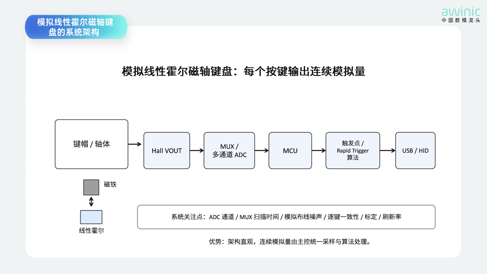
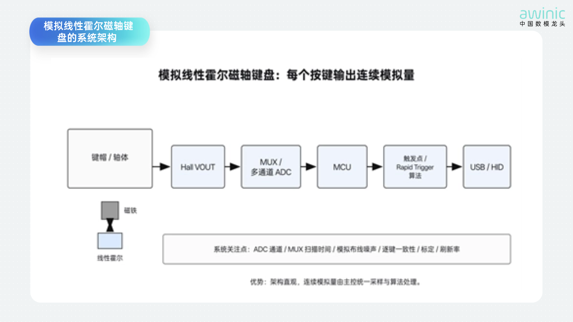
The key to magnetic axis keyboards is not simply“replacing springs with magnets”, but rather utilizing the magnet within the switch to move up and down with the key press, causing the linear Hall sensor on the PCB PCB to output a continuous change. The main controller calculates the trigger and release positions based on the real-time travel of each key, thereby enabling functions difficult to achieve with traditional mechanical contacts, such asadjustable trigger points, rapid trigger (Rapid TriggerRT), and dynamic dead zones
. 6 Figure
-
System architecture of analog linear Hall magnetic axis keyboards
-
Per-key analog output directly reflects switch travelThe main controller can perform individualzero-point, full-scale, and curve calibration
-
Rapid Trigger for each key to compensate for magnet and assembly tolerances/. The core principle is to dynamically set trigger and
-
release conditions based on the current key travel and movement direction, rather than relying on fixed mechanical contacts MCU ADC . Large keyboards have many channels, requiring careful evaluation ofMUX ADC quantity,
scan time, sample-and-hold performance, analog noise, ground bounce, and refresh rate + Typical Application 4: Digital Linear Hall Sensors
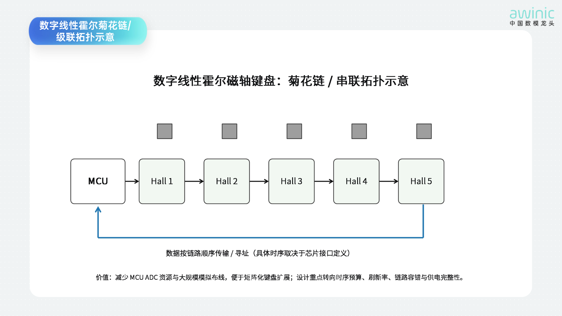
Daisy-chained magnetic axis keyboards ADC When the number of keys expands from dozens to a full keyboard array, theMCU resources and analog wiring complexity of analog solutions increase rapidly“. Linear Hall sensors supporting digital output and multi-device daisy chaining can convert”per-key analog sampling“into reading multiple digital nodes over a link”, reducing the pressure on large-scale analog channels from the system architecture perspective.
Figure 7 Digital Linear Hall Daisy Chain/Schematic of Cascaded Topology
A daisy chain does not imply that all products adopt exactly the same electrical interface. Chips can build multi-device links based on dedicated serial timing, cascaded data input/output, or addressable buses. For magnetic axis keyboards, key system design metrics include:full-chain scanning cycle, single-key effective refresh rate, maximum chain length, clock frequency, data integrity, supply voltage drop, link fault isolation, and power-on enumeration/calibration time.
If digital linear Hall sensors can perform effective zero-point, sensitivity, and temperature drift calibration on-chip, the complexity of handling per-key analog link consistency can also be reduced. For solutions aiming to reduce MCU ADC resources, simplify PCB analog routing, or expand to more key nodes, this architecture offers significant appeal.
awinic Linear Hall Products and Selection Recommendations
Recommended Analog Linear Hall
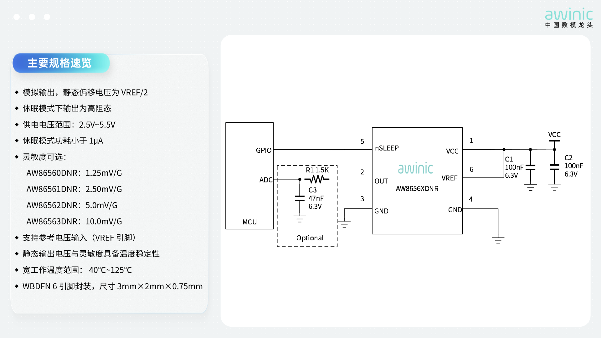
AW8656XDNR is a linear Hall effect integrated circuit whose output changes proportionally with magnetic induction intensity; the device's static output voltage is VREF of the nominal value of the ratiometric supply reference voltage applied to the 50%pin.
The device consumes 2.6mAin active mode and supports user-configurable sleep mode, which can reduce current consumption to below 1μA . The chip features magnet temperature compensation capable of offsetting magnet temperature drift, ensuring linear performance across a wide temperature range of-40℃~+125℃; device versions without magnet temperature drift compensation are also available.AW8656XDNR It adopts a 6 -pin DFN package, with an operating temperature range of‑40℃~+125℃, and lead-free package versions are provided.
Recommended Digital Linear Hall
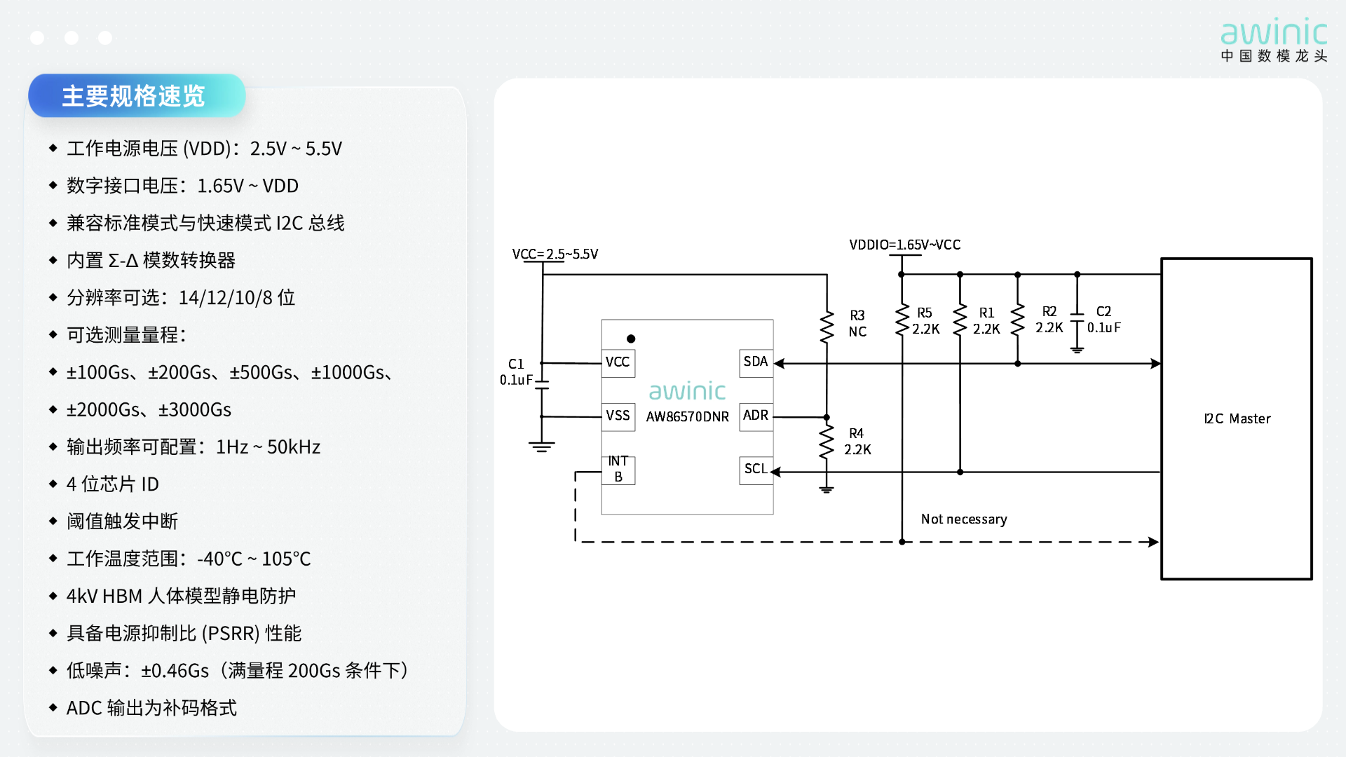
AW86570 is a high-speed, high-sensitivity magnetometer chip based on the Hall effect, featuring a built-in 14 -bit ADC, with a maximum operating frequency reaching 50kHz. The magnetic field detection range is configurable from ±100Gsto±3000Gs, enabling simultaneous detection of N and S pole magnetic fields.
AW86570 The supply voltage supports 2.5V~5.5V, and theVDDIO interface voltage can be as low as 1.65V. It is equipped with a 1MHz bus supporting communication rates up toI²C and includes a hardware interrupt pin configurable for bidirectional threshold detection. The chip has an operating temperature range of‑40℃~+105℃, features 4kV ESD protection capability, and adopts a 1.6mm×1.6mm×0.55mm DFN package.
Conclusion
From three-stage shoulder keys to sub-millimeter sliders, from single knobs to magnetic axis keyboards with hundreds of keys, the fundamental problem solved by linear Hall sensors remains consistent:stably mapping mechanical displacement into computable magnetic field information. Analog linear Hall sensors emphasize simple, direct continuous voltage output, while digital linear Hall sensors shift more sampling and calibration capabilities down to the sensor end. As consumer electronics demand grows for contactless operation, long lifespan, programmable interaction, and multi-node sensing, linear Hall sensors are evolving from traditional position detection devices into“continuous position sensing interfaces”within human-machine interaction systems.