As summer arrives, the peak season for mountain riding, the cycling community is experiencing a silent“wave of camera failures”: After a few long-distance rides with flagship phones mounted on the handlebars, camera issues arise first —— The image continuously shimmers like water ripples, focus hunts back and forth repeatedly, faint mechanical noises emanate from within the lens, and repairs typically determine it aspermanent mechanical damage to the stabilization and autofocus systems.
The issue is not quality control. Apple has already explicitly warned in its official technical support documentation (HT212803) that high-amplitude vibrations generated by high-power motorcycles can permanently damage the iPhone optical image stabilization (OIS) and closed-loop autofocus systems, thereforeit is not recommended to mount phones directly on handlebars or frames.
A counter-intuitive question follows: Since phones prominently feature“ultra-strong stabilization”, why can't they withstand motorcycle vibrations?
I. Breaking Cognitive Barriers: Stabilization≠and vibration resistance are fundamentally two different things
90% Misunderstandings stem from confusing two concepts:Stabilization is for“compensating slight jitters”, while vibration resistance is for“withstanding powerful impacts”. Phones OIS from day one of their existence, have never aimed to“withstand engine vibrations”.
OIS Design boundaries: Tailored exclusively for“hand tremors”:
Optical Image Stabilization (OIS) essentially builds a micron-level floating compensation system within the lens module: movable lenses (or sensors) are suspended via metal leaf springs, working with gyroscopes and electromagnetic drive structures to detect hand shake and move inversely by a few microns to offset image shift.
All parameters of this system are strictly optimized around“handheld shooting”:
-
Operating frequency range: Covers only1~20Hz low-frequency jitters, with energy concentrated around 8Hz , corresponding to the amplitude of physiological tremors when holding a phone by hand
-
Compensation travel: Single displacement is only a few microns, less than1/10
-
of a hair's diameter0.5gTolerable acceleration: Designed peak is only about
, more than sufficient for daily hand shake and walking motion
-
So what do motorcycle engines bring?20~120Hz Vibration frequency: From idle to high RPM covers Hzwide-band vibrations, secondary vibrations from the transmission system can reach over a thousand OIS , completely exceeding the
-
operating frequency range3~10m/s²Continuous acceleration: Effective vibration acceleration values at the handlebars can reach( 0.3~1gapproximately 3g), with peaks breaking through , several times that of handheld scenarios
-
Instantaneous impact: When crossing potholes or speed bumps, the impact acceleration can reach10g+, which is dozens to hundreds of times the designed tolerance value
To put it in perspective:OIS It's like a precision electronic balance in a laboratory, incredibly accurate for weighing milligram-level reagents; but if you insist on mounting it on a pile driver, it's not that the balance is of poor quality, but that you have directly breached its physical design limits.
Image source: Bilibili (bilibili) Creator @Victory Wenzhouzhou
II. Triple Critical Hit: How High-Frequency Vibration Destroys Image Stabilization Step by Step
A perfectly intact OIS structure damaged under continuous high-frequency vibration is essentially the result of three overlapping physical mechanisms, interlinked and mostly irreversible.
1. The Primary Killer: Resonance Amplification Turns Micrometer-Level Micro-Movements into Violent Impacts
This is the core damage mechanism and the most easily overlooked physical law.
Every suspension structure has a fixed natural resonant frequency—— Just like swinging on a swing, applying force at the natural frequency drastically amplifies the amplitude. Academic tests show thatmainstream wire-suspendedOISsystems have a natural frequency of approximately60Hz+; during design, only the 1~20Hz low-frequency range of hand tremors was deliberately avoided, leaving them completely unprotected against mid-to-high frequencies.
However, the engine vibrations of single-cylinder and twin-cylinder motorcycles just happen to cover the 20~120Hz wide frequency range, making it highly likely to overlap with the natural frequency of the OIS , triggering a resonance effect.During resonance, the amplitude of internal moving parts is amplified dozens of times; what was originally a smooth micrometer-level movement becomes a violent reciprocating impact.
Continuous alternating stress rapidly induces metal fatigue: leaf springs and suspension structures repeatedly endure pulling forces beyond their design limits. Like an iron wire bent back and forth, this quickly leads to leaf spring fracture, ball bearing detachment, and magnet displacement. At best, the image stabilization function fails completely; at worst, the lens assembly jams directly.
2. Over-Travel Hard Impact: Directly Shattering Precision Structures
If resonance is“chronic blood loss”, then road impacts are“instantaneous critical hits”.
The instantaneous impact generated when crossing speed bumps, hitting potholes, or braking suddenly can produce accelerations up to20~50g; the suspended lens / sensor will slam violently against the module's mechanical hard stops with immense force. A single impact might not cause immediate damage, but repeated collisions cause irreversible hard damage:
-
Mechanical stop structures wear down and shatter, losing their buffering effect
-
Optical lenses become misaligned or chipped, causing light path deviation and permanent image blur
-
VCM Motor coils desolder, and Hall sensors for position detection fail; not only is image stabilization ruined, but autofocus functionality also becomes inoperative simultaneously
3. Lubrication Dries Up + Electrical Fatigue: Accelerating Complete Failure
OIS The ball guide rails and leaf spring moving parts of
are coated with only a微量 amount of specialized lubricating grease, originally designed for low-frequency, small-amplitude reciprocating motion.
Continuous high-frequency vibration generates strong centrifugal force, causing the lubricating grease to be quickly flung off and dry out. Once metal parts lose lubrication, they grind directly against each other, causing wear rates to rise exponentially. Soon, structural jamming, increased clearance, and loss of stabilization precision occur, ultimately leading to complete seizure.FPCMeanwhile, precise electrical components within the module, such as flexible flat cables ( IC ), micro solder joints, and drive —— units, endure repeated bending stress under continuous high-frequency vibration, much like a data cable being bent back and forth.
Eventually, this leads to intermittent image stabilization failure, complete system crashes, and in severe cases, can even cause a short circuit in the entire camera module.
III. The Overlooked Companion in Distress: The Autofocus System is Equally Fragile OISIn Apple's official documentation, besides, the closed-loop autofocus system was specifically highlighted. Many people know that image stabilization fears vibration, but overlook the fact thatthe autofocus motor is essentially also a suspension structure
, and thus equally vulnerable to high-frequency vibration.VCM) estimates the lens position by current, which has limited accuracy; while flagship phones'closed-loopAFsystems incorporate Hall position sensors, providing real-time feedback on lens position for faster and more accurate focusing. However, its core remains a movable lens group suspended by spring sheets, belonging to the same category of floating mechanical systems as OIS .
Industry data shows thatmobile phoneAFautofocusVCMsystems typically have a natural resonant frequency in the range of50~150Hz, with a typical value around 76.4Hz, which also falls perfectly within the vibration frequency band of motorcycles. High-frequency vibrations cause direct damage:
-
motor spring sheets fatigue and fracture, preventing lens movement and causing complete autofocus failure
-
Hall sensors shift or solder joints detach, causing the autofocus system to lose position feedback and become completely uncontrollable
-
even if not completely damaged, long-term vibration leads to increased motor gaps, slower focusing, repeated hunting, and permanent image blur
IV. Where Lies the Future Path
Just because it cannot be done now does not mean it cannot be achieved in the future. To enhance the anti-shake capability of imaging systems,AF/OISsolutions require comprehensive upgrades across three dimensions:hardware,motors, andalgorithms.
1.Enhancement of Hardware Capabilities
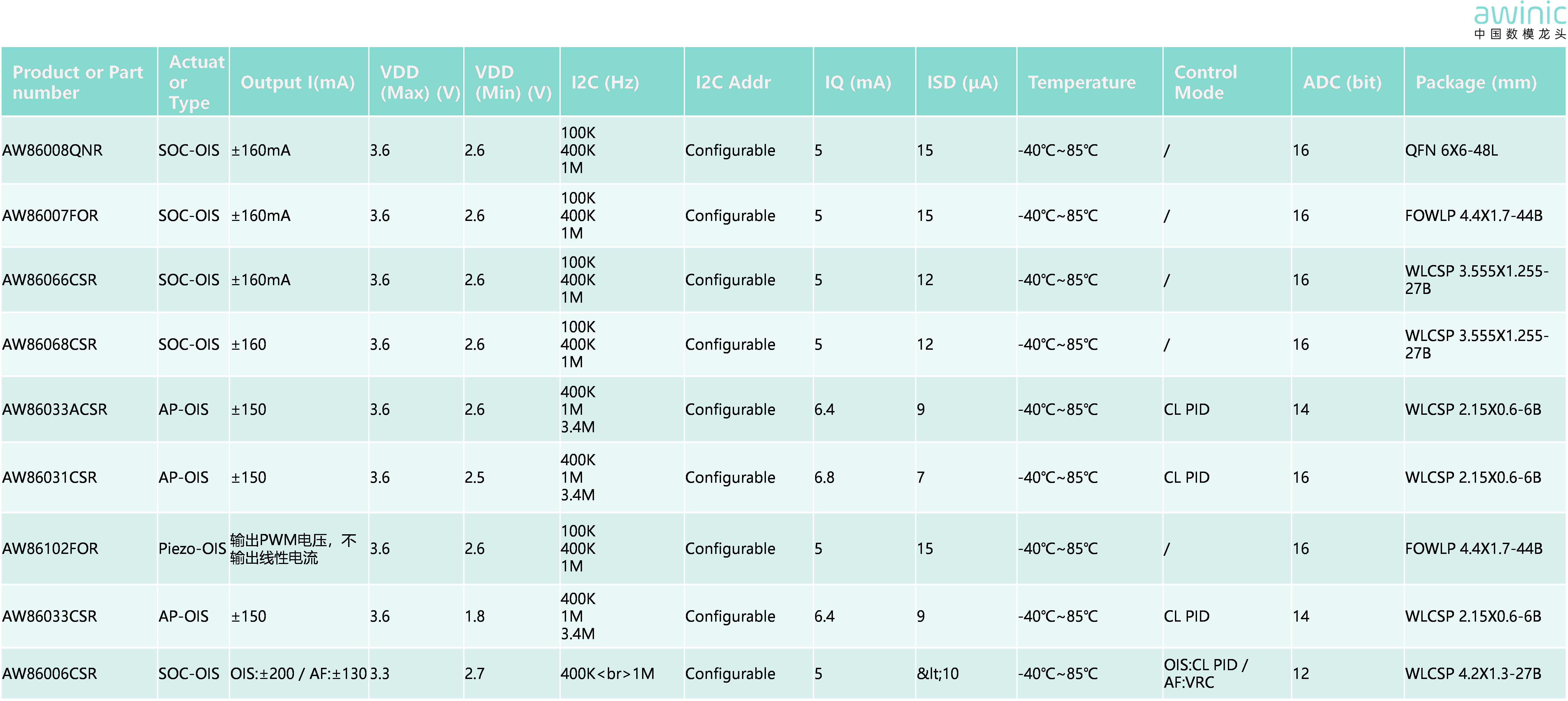
Traditional AF/OIS systems Driver IC have drive current ranges in100~200mA. According to the Lorentz force calculation equation:
F=BIL=ma
the maximum drive current supported by the driver chip determines the upper limit of motor acceleration. To improve the module's resistance to vibration and shock, one must firstincrease the upper limit of maximum drive current supported at the hardware level.
2.Improvement of Motor Characteristics
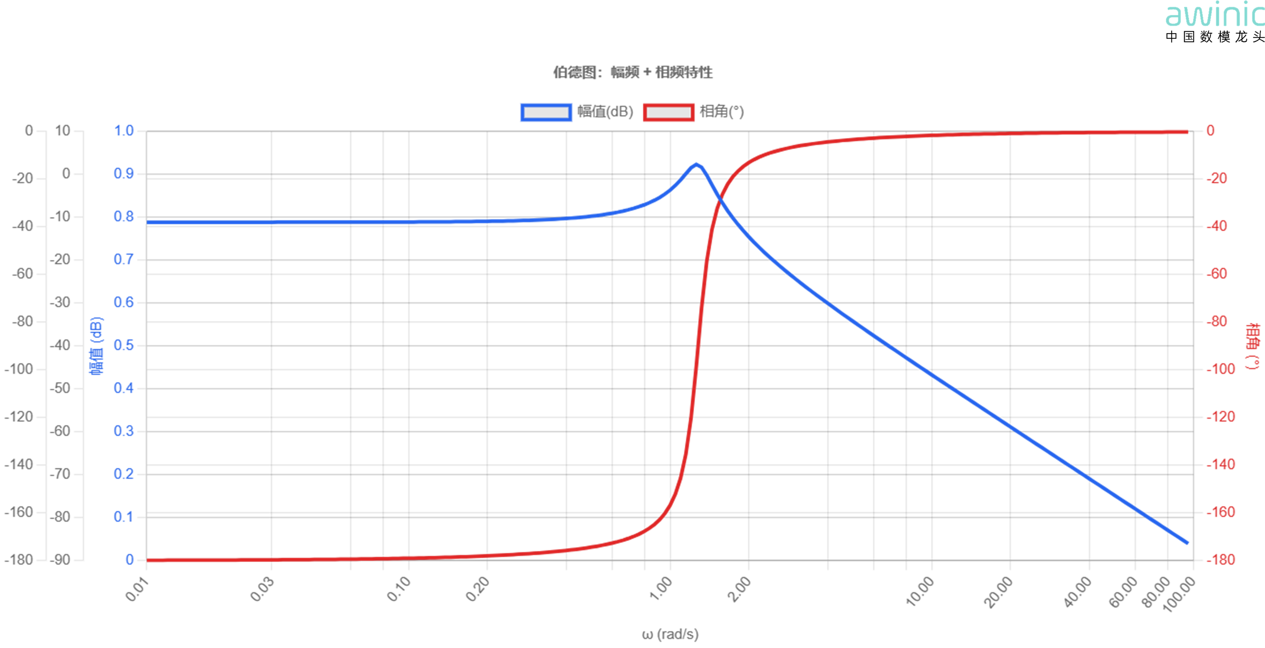
Currently, the spectral characteristics of mainstream motors approximate a third-order low-pass system, with cutoff frequencies between80~100Hz. Considering that engine vibrations from single-cylinder and twin-cylinder motorcycles are mainly distributed within the 20~120Hz wide frequency range,therefore, in motor design, appropriatelyenhancing the motor's resonance capability in the80~120Hzrange, i.e., introducing aQ0pointin the structural configuration dimension, can improve the motor's response capability in the mid-frequency region, thereby quickly counteracting random vibration interference caused by external disturbances.
3.Improvement of Control Algorithms
The open-loop spectral characteristics of traditional control algorithms are shown in the figure below. As seen from the figure,servo strategies mainly focus on optimizing and improving response capabilities within30Hz, while response capabilities within80~120Hzattenuate rapidly.
To effectively improve the system's response capability in the mid-frequency region, the control algorithm design can be refined to increase the gain bandwidth of the overall open-loop spectral amplitude-frequency response to around100Hz, strengthening the system's anti-shake bandwidth to meet the demands for responding to severe vibrations in the mid-frequency segment.