1.Introduction: When Ambient Lighting Meets“Color Difference”Challenge
Imagine this scenario: You step into a new car equipped with ambient lighting. The inner door panels glow with a soft ice blue, while the center console emits a slight cyan hue. Despite being set to the same color, the LEDs at different positions display subtle variations. This is certainly not the experience expected by automakers or consumers.
Vehicle ambient lighting typically usesRGB LEDas the light source, mixing millions of colors by adjusting the brightness ratios of the three primary colors:Red, Green, Blue. Theoretically, providing the same drive configuration to LEDs of the same model should result in identical colors. However, in reality,LEDunavoidable process deviationsexist duringmanufacturing. Even LEDs from the same batch and the sameBinbin exhibit differences in their luminous characteristics.
Color calibration technologywas born precisely to address this pain point. By creating a“personalized profile”for each LED during the module production phase and presetting calibration parameters into the driver chip, it ensures that different LEDs can accurately render the target color after color mixing.
2. WhyLEDis the color inconsistent?
2.1 Individual LED Differences-“Innate Deficiencies”
Due to fluctuations in semiconductor manufacturing processes, even LEDs from the sameBinbin (batches graded by brightness and/wavelength) exhibit dispersion in their actual color coordinates and luminous flux.
For example: Suppose the target color is“Amber Orange”, requiringR:G:Bcolor mixing in a specific ratio. If one LED has a stronger red chip and a weaker blue chip, while another is exactly the opposite, the colors displayed by both under the samePWMconfiguration will be reddish for one and bluish for the other.
Figure1 Variation in target color presentation across different LEDs
Without using a color mixing algorithm,the color coordinate deviation of thetarget color can reach±0.2, which is easily noticeable to the naked eye and seriously affects the refinement of the vehicle's interior.
2.2 Temperature Drift-“Acquired Changes”
LEDThere is another characteristic: the longer the lighting duration, the higher the chip junction temperature, causing changes in its emission wavelength and brightness. In anRGBRGB color mixing system, the drift characteristics of the three colors are not synchronized; originally balanced white light may gradually shift towards blue, amplifying the color deviation problem manifold.
The operating temperature range for automotive interior lights is typically required to cover-40℃~+120℃. In extreme cold starts or after exposure to scorching summer sun, without temperature compensation, the LED color may deviate significantly from the design value.
3. Core Concepts of Color Calibration
3.1 CIE 1931: Giving Color a“Standard Address”
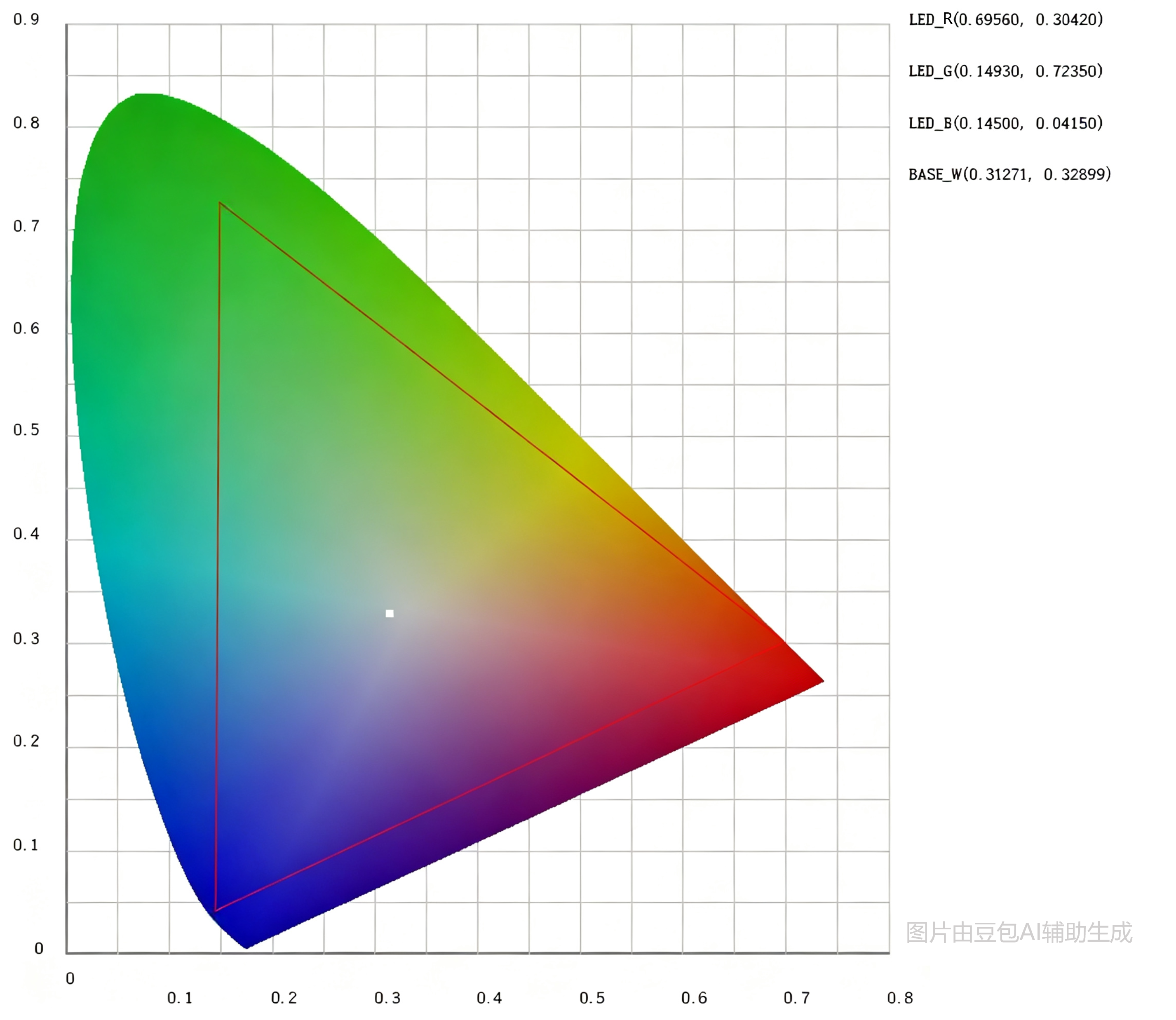
To ensure color description is no longer“based on feeling”, the International Commission on Illumination (CIECIE1931) established a standard colorimetric system inCIE 1931 1931(x, y): the CIE 1931 color space. It uses a horseshoe-shaped two-dimensional chromaticity diagram to represent all colors visible to the human eye, where every point in the diagram corresponds to a unique color coordinate (x, y).
Figure2 CIE 1931Chromaticity Diagram
Simple understanding:CIE 1931Just like a color's“Amap”, as long as you report the(x, y)coordinates, the whole world knows which color you are referring to.
The automotive ambient lighting industry generally adopts this standard for color definition. When car manufacturers issue color requirements to suppliers, they usually do not say“"I want a warm white"”, but instead provide precise chromaticity coordinate ranges, such as (0.440, 0.400)± 0.01.
3.2 Light mixing algorithm: From target color toPWMduty cycle
RGBLight mixing follows the principle of additive color mixing: by adjusting theR、G、Bthree-channelPWMduty cycles, the luminance contribution of the three primary colors is regulated, ultimatelyCIEon the“chromaticity diagram”to locate the target color coordinates.
Its core approach can be summarized in three steps:
Figure3 Light Mixing Algorithm Flowchart
Since theR/G/Bprimary color coordinates of each LED bead differ, the requiredPWMratio for the same target color also varies across different beads. The key to the light mixing algorithm is to calculate the exclusive“configuration”for each bead based on itsPWMindividual parameters
4. Color Calibration Practical Process
So, how are these“individual parameters”obtained? The answer is:Calibration is completed on the module production line.
4.1 Pre-calibration Preparation
Calibration requires professional optical measurement equipment: a spectrometer, which can quickly and accurately read the chromaticity coordinates and luminous flux data of illuminated LED beads.
4.2 Core Calibration Steps
Taking a singleRGBLED bead as an example, the calibration process is as follows:
Figure4 Production Line Calibration Steps
Key Notes:
1. Data is collected at maximum duty cycle (100%) to obtain the maximum luminous flux and chromaticity coordinates of each primary color, serving as the core calibration parameters for the LED bead.
2. The verification stage involves random sampling of several target colors for re-testing to ensure that the deviation between the actual mixed color result and the target color coordinates falls within the allowable range.
4.3 Post-calibration Effects
After calibration is completed, the driver chip automatically calls the pre-stored calibration parameters during operation and, combined with the built-in light mixing algorithm, calculates in real-time the precisePWMConfiguration.
awinicThe self-developed color mixing algorithm, verified by actual spectrometer measurements,can control the chromaticity coordinate deviation of the target color within±0.005,which is far smaller than the threshold perceptible to the human eye (approximately±0.01), truly achieving high consistency in LED colors across different modules and positions.
5.Temperature Compensation: Color Guardianship Across the Full Temperature Range
Color calibration solves the“consistency issue at room temperature”, but automobiles must also face extreme temperature environments.awinicawinic's solution is the temperature compensation algorithm.
5.1 Principle of Temperature Compensation
LEDThere is a clear correspondence between the junction temperature of awinicPNand the junction voltage. By collecting the junction voltage and corresponding optical color parameters of each LED point-by-point within the-40℃~+120℃range with a step size of1℃, a temperature compensation parameter table (LUT) can be established for each LED.
Figure5 Temperature Compensation Workflow
When the chip is operating, it monitors the LED junction temperature in real-time, automatically calls the corresponding temperature compensation coefficient, and dynamically adjusts thePWM, thereby ensuringthat the target color remains basically unchanged across the-40℃~+120℃full temperature range.
6. awinicSolution: One-Stop Color Management
Based on the aforementioned color calibration and temperature compensation technologies,awinicawinic integrates them into automotive-grade chips to provide customers with a one-stop solution: Taking the automotive-grade chipAW23003QNR-Q1as an example, it is a highly integratedLIN RGB SoCcontroller with built-incolor calibration algorithmandLED temperature compensation algorithm. Customers can achieve precise and consistent optical color output without needing to develop complex software additionally at the module level.

Figure6 awinicSolution Architecture
7. Summary
LEDColor calibration is essentially a precision engineering task that ensures every LED remains faithful to the design. From single-point calibration on the production line to dynamic temperature compensation during driving, every link safeguards the final user experience.
For automakers andTier 1suppliers, choosing a chip partner with mature color mixing algorithms and temperature compensation technology means significantly shortening the development cycle of ambient lighting modules, reducing production testing complexity, and ensuring the consistency of interior light quality across the entire vehicle.