During audio device debugging and production-line testing,mute faults are high-frequency, hard-to-resolve pain points—no sound output at all, which delays progress more than noise or distortion. The entire signal chain—from audio source to speaker—involves multiple modules including software, algorithms, hardware, and components; failure at any single point causes the fault, and blind troubleshooting easily wastes time.
This article compiles apractical, ready-to-deploy troubleshooting procedure for audio mute faults, covering scenario classification, node-level diagnostics, root-cause analysis, and resolution methods. It applies comprehensively to daily debugging, production-line stress testing, and firmware version iterations—engineers can follow step-by-step to rapidly locate and resolve issues.
I. First, Categorize: Common Mute-Fault Scenarios
First clarify the fault scenario to avoid directionless troubleshooting. Below are thesix most frequent mute-fault categories, all diagnosable via standardized signal-chain inspection:
- Basic Playback Mute: No sound during local music or video playback
- Call Voice Mute: No voice output during voice calls or VOIP calls
- Scenario-Switch Mute: Sudden mute after switching from Normal mode to Voice mode, or after switching between Douyin/WeChat voice channels
- Intermittent Mute Fault: Occasional mute during production-line stress testing or after prolonged device operation
- Version-Iteration Mute: Complete mute after baseline upgrade or firmware update
- Peripheral-Associated Mute: Single-ear mute upon headphone insertion; mute of external speaker after headphone removal
II. Core Signal Chain: Five Key Diagnostic Nodes
As shown in Figure 1 below, most common mute faults map to thestandard audio signal chain, divided into five key nodes in signal transmission order. Thecore diagnostic principle is identifying the“first node with no signal”—eliminating the need for blind full-chain inspection.
Signal-Chain Logic: Audio Source PCM → Platform Volume Control (Node A) → Platform Audio Effect Algorithm Processing (Node B) → Signal Output Transmission (Node C) → Power Amplification (Node D) → Terminal Output Wiring (Node E) → Speaker Output.

' fill='%23FFFFFF'%3E%3Crect x='249' y='126' width='1' height='1'%3E%3C/rect%3E%3C/g%3E%3C/g%3E%3C/svg%3E)
Figure 1 Typical Audio Signal Chain Diagram
Node-Type Classification:
- Nodes A & B: Pure digital-signal nodes internal to the platform
- Node C: I²S digital signal / Codec DAC analog signal (digital/analog boundary)
- Nodes D & E: Analog-signal nodes (power amplifier, wiring, etc.)
III. Practical Steps: Node-by-Node Diagnostic Methods
Perform diagnostics sequentially by node, using corresponding tools to verify signal integrity—simple operations with intuitive results, enabling rapid onboarding even for newcomers.
1. Diagnosing Nodes A & B (Digital Nodes)
Tool: Platform Audio Log Capture Tool
Procedure:
- Directly capture platform audio logs and analyze whether PCM signals at the node are valid
- Capture methods vary across platforms; if uncertain about procedures, contact platform software colleagues or technical support for assistance
2. Diagnosing Node C (Two Signal Types)
(1) I²S Digital Signal
Tool: AP Digital Interface, Oscilloscope
Procedure:
- Capture I²S signals using the AP digital interface and check signal integrity
- Rapid check: Use an oscilloscope to probe the I²S lines—stable square-wave output indicates normal signal; absence of square wave = signal interruption
(2) Codec Analog Signal
Tool: AP Analog Interface, Multimeter (AC setting)
Procedure:
- Capture analog signals at the Codec output using the AP analog interface to confirm signal validity
- Rapid check: Set multimeter to AC mode and test for AC voltage across AP terminals—voltage present = normal signal; no voltage = abnormal DAC conversion
3. Diagnosing Nodes D & E (Analog Nodes)
Tool: AP Analog Interface, Multimeter (AC setting)
Procedure:
- Capture analog electrical signals at the node using the AP analog interface and verify signal integrity
- Rapid check: Use multimeter’s AC setting to measure node voltage—voltage present = normal signal; no voltage = abnormal signal transmission
IV. Precise Resolution: Root-Cause Analysis & Corresponding Remediation per Node
Once the faulty node is identified, directly match it with its root cause and remediation method—then engage the responsible personnel to resolve the issue. Details are shown in Table 1 below.
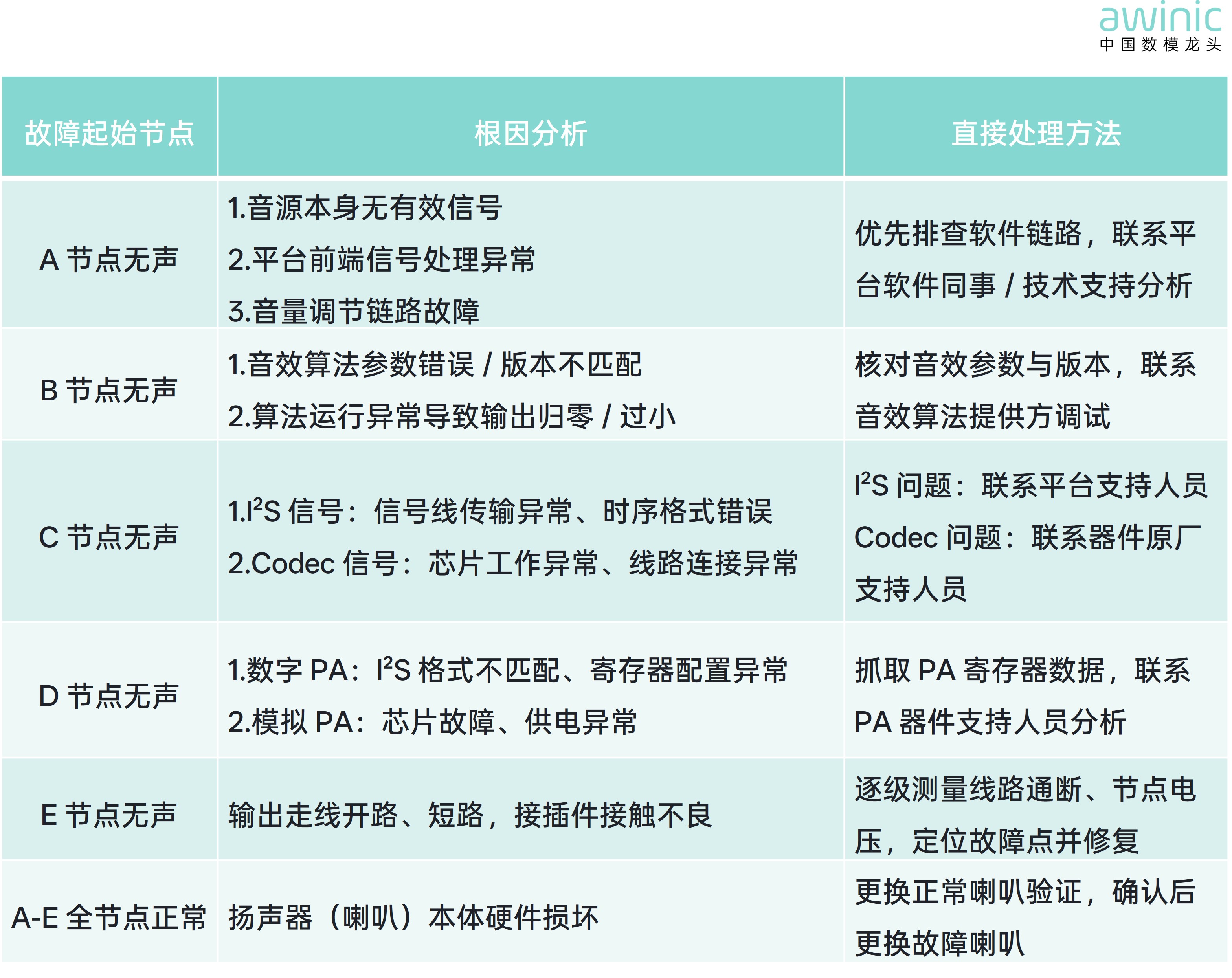
Table 1 Root-Cause Analysis and Remediation Methods
V. Closed-Loop Verification: Mandatory Post-Fix Validation
After resolving the issue, mandatoryclosed-loop verification must be performed to ensure complete fault resolution:
- Re-trigger the original fault scenario (e.g., scenario switch, version upgrade, stress test)
- Verify normal audio output and confirm end-to-end signal-chain integrity
- Document root cause and resolution steps for rapid future diagnosis of similar issues
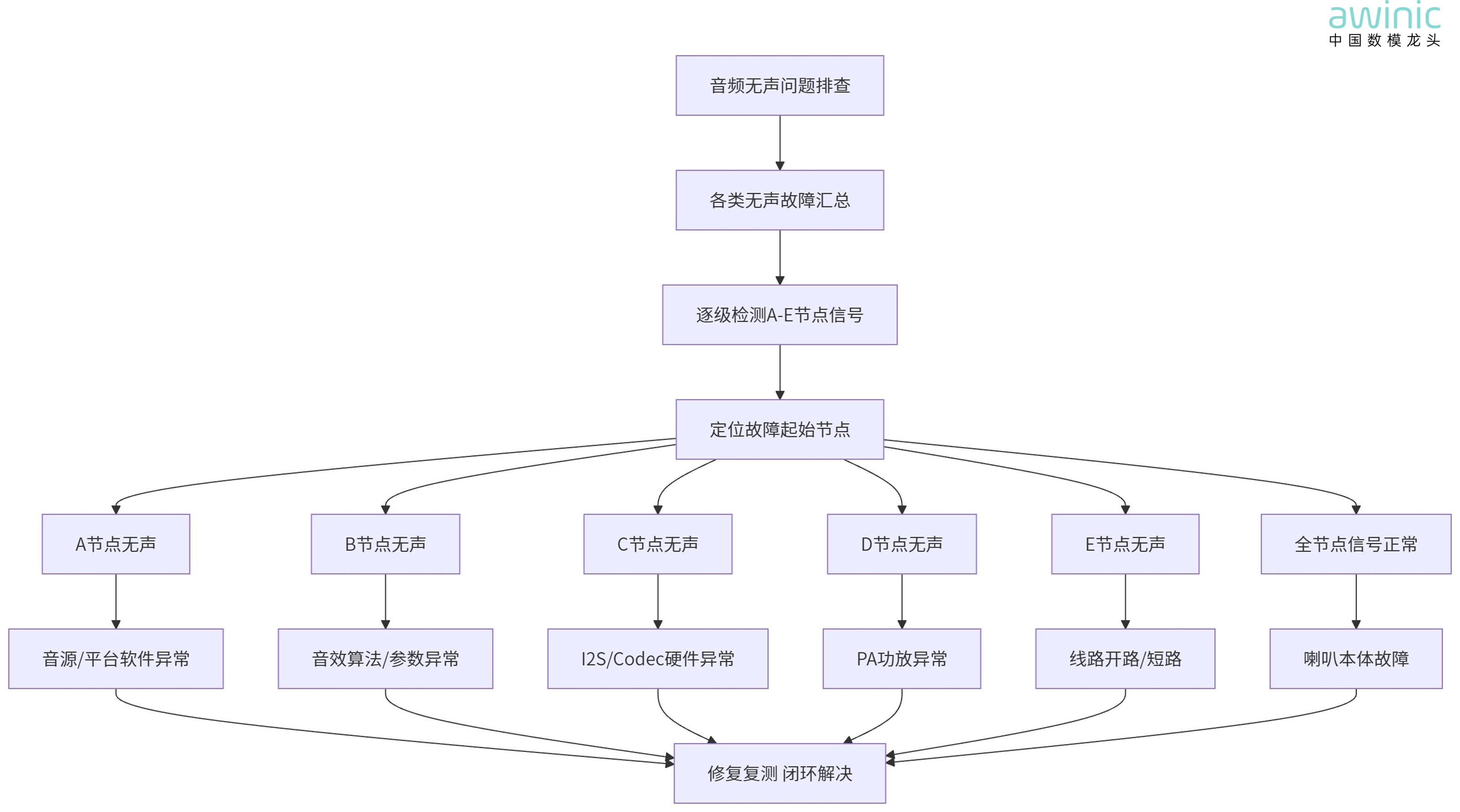
Figure 2 Standardized Troubleshooting Flowchart for Audio Mute Issues
Though audio mute faults appear complex, they become manageable once you grasp the core logic: “First identify the node, then diagnose the root cause, and finally apply targeted resolution.” This approach resolves typical cases efficiently.
This procedure synthesizes frontline debugging experience and fits most audio devices—directly applicable to daily debugging, production-line issues, and version iterations.