As AI PC computing power continues to
surge and performance is fully unleashed, device power consumption and
recharging demands have increased significantly. High-power fast charging has
become an irreversible industry trend. Traditional fast charging specifications
below 100W can no longer meet the usage needs of high-performance AI terminals.
PC fast charging power has officially entered a phased upgrade path, forming a
65W → 100W → 140W → 180W → 240W progression, fully covering the high-power
power-supply scenarios of AI PCs, high-performance ultrabooks, gaming laptops,
and multi-function docking stations.
AWINIC Type‑C OVP Series Products
The technological driver behind this
power upgrade stems from the continuous iteration of the USB PD protocol. Charging
voltage has also undergone a critical specification leap, advancing from 20V
(SPR) → 28V (EPR) → 36V (EPR) → 48V (EPR). Among these, the PD3.1 SPR 20V
specification suits 65W‑100W conventional fast‑charging scenarios, while the
new PD3.2 EPR 28V/36V/48V high‑voltage specifications help devices break
through power bottlenecks, supporting 140W‑240W and above ultra‑high‑power fast
charging, greatly improving charging efficiency and overall system power supply
stability. In response to this industry upgrade trend, AWINIC has launched a
series of fast‑charging protection products that meet SPR 20V and EPR 28V
charging voltage requirements, cover 140W‑180W charging power applications, and
precisely align with the design needs of next‑generation AI PC fast‑charging
systems.
Leveraging its core advantages of
universality, high speed, and high integration, the Type‑C interface has become
the standard port for AI PCs and docking stations, with multiple Type‑C ports
operating in parallel being a mainstream hardware design. The new operating
conditions of 28V high voltage + high power + multi‑port concurrent operation
have dramatically increased the protection pressure on the device power supply
system. Traditional simplistic protection schemes can no longer adapt to the
demanding high‑voltage fast‑charging environment. The industry now demands high‑robustness
design standards for systematic safety protection of Type‑C interfaces.
To ensure the long‑term safe and stable
operation of AI PCs and docking stations under high‑voltage, high‑power fast‑charging
scenarios, hardware designs must be equipped with four core protection
capabilities, building a comprehensive power‑safety defense line:
I. Adapt to Multi‑C‑Port Application
Scenarios
Adopt a back‑to‑back structure OVP
protection that is compatible with multi‑port parallel charge/discharge
operating conditions.
II. Equip Fast Over‑Voltage Protection
Combine strong surge protection and ESD
protection capabilities to provide high‑robustness safety protection for the Type‑C
input stage and downstream circuits, guarding against various high‑voltage
anomalies and electrical disturbances.
III. Integrate Reverse‑Current Blocking
Protection
Effectively prevent current backflow,
avoiding damage to the chip and the overall system.
IV. Include Short‑Circuit Protection as
Standard
Quickly handle faults such as
plug/unplug anomalies and line short circuits, comprehensively covering all
safety hazards in high‑power fast charging.
Product Advantages
1. Fast Over‑Voltage Protection
AWINIC AWP3210x Product
With external TVS SP1224, VIN = 20V, VIN
surge = 100V, Rload = 100Ω, CIN/COUT = NC
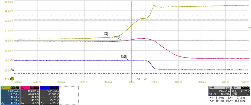
Figure 1 AWINIC Solution OVP Response
Time
OVP response time: 27ns, VIN max =
26.28V, VOUT max = 22.81V
Other Industry Solutions
With external TVS SP1224, VIN = 20V, VIN
surge = 100V, Rload = 100Ω, CIN/COUT = NC
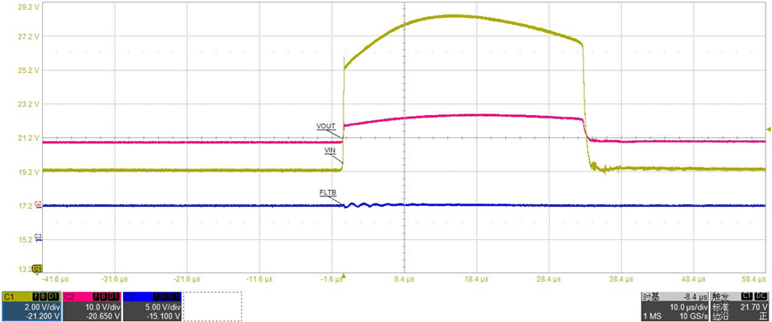
Figure 2 Other Industry Solution OVP
Response Time
OVP response time: >1μs, VIN max =
28.5V, VOUT max = 27.6V
2. Dual Protection Advantages: Ideal
Diode + Fast RCP
This is not merely a superposition of
two functions, but a precise solution to a core pair of contradictions in OVP
protection product design: efficient power delivery under normal conditions
versus self‑preservation under catastrophic faults. The two independent
mechanisms cover two completely different application scenarios.
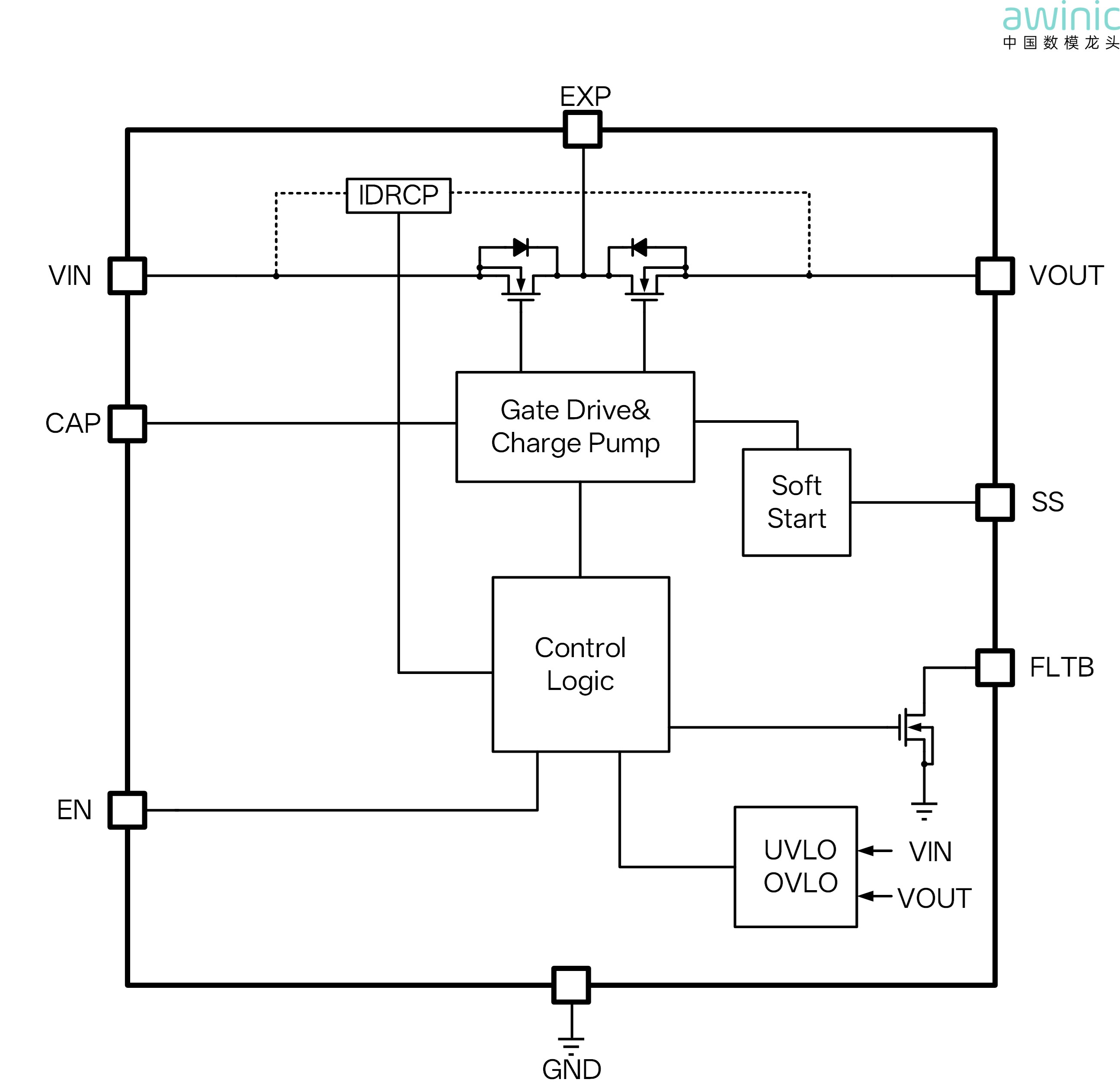
Figure 3 AWINIC OVP Protection Scheme
Ideal Diode:
Addresses Slowly Varying Anomalies,
Provides Efficient Normal‑State Anti‑Reverse‑Current Protection
When the adapter is unplugged or during
voltage dips, the system‑side stored energy tends to backflow. In mild cases,
this causes abnormal indications; in severe cases, it can damage the front‑end
circuitry through reverse current. Traditional solutions rely on Schottky
diodes, which generate severe heat under high current and pose thermal runaway
risks at high temperatures.
Advantages:
Real‑time closed‑loop regulation of
MOSFET gate voltage maintains an extremely low and stable forward voltage drop.
Performance does not degrade under high‑temperature full‑load conditions,
eliminating thermal runaway in principle and achieving efficient, smooth,
seamless switching.
Fast RCP:
Addresses Extreme Short Circuits with
Nanosecond‑Level Ultra‑Fast Hardware Protection
When VBUS is shorted to ground, the
current surges with an extremely high di/dt. If relying only on microsecond‑level
turn‑off protection (Ideal Diode response time), the reverse surge can
instantly reach tens to hundreds of amperes—enough to melt bonding wires,
destroy MOSFETs, burn PCB traces, and even cause complete system failure.
Advantages:
Senses and instantly cuts off the
reverse path at nanosecond speeds, completely blocking energy before a
destructive impact forms, providing the final safety barrier for both the chip
itself and the overall system.
The Ideal Diode handles
routine efficient power delivery and smooth transitions, while Fast RCP ensures
survival under extreme fault conditions. The two are layered and complementary,
forming a complete protection closed loop from normal operation to catastrophic
scenarios.
3. Input and Output Surge Protection
Mechanism Enhanced by AWINIC’s Patented Technology
The chip integrates built‑in surge
protection, using an internal Q3 to equivalently replace the external TVS. A
single component protects against surges on both the VIN and VOUT terminals,
saving components, saving board area, and enabling a more streamlined design.
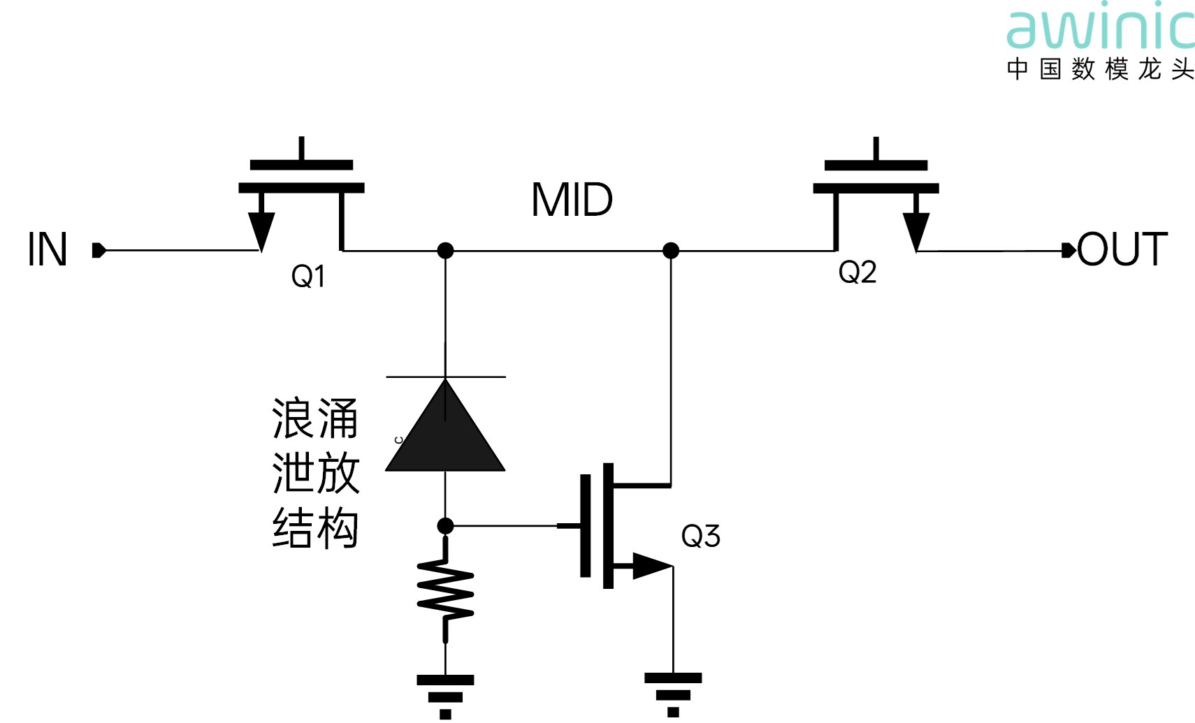
Figure 4 AWINIC Surge Discharge
Structure
Product Introduction – AWP32107DNR
·
Wide Input Voltage range from 3.4V to 23V
·
8A continuous current capability
·
VIN and VOUT are rated 38V Abs max
·
Integrated ultra‑low Ron switch: typical 17mΩ
·
Over‑Voltage Protection turn‑off response: typical 100ns
·
Ideal Diode RCP
·
Programmable soft‑start
·
VIN Under‑Voltage Lockout (UVLO)
·
Over‑Temperature Protection (OTP)
·
Short Circuit Protection
·
IEC 61000‑4‑2 Contact Discharge ±8KV
·
IEC 61000‑4‑5 45V Surge Protection on VIN and VOUT
·
Thermally enhanced DFN3×3‑12L
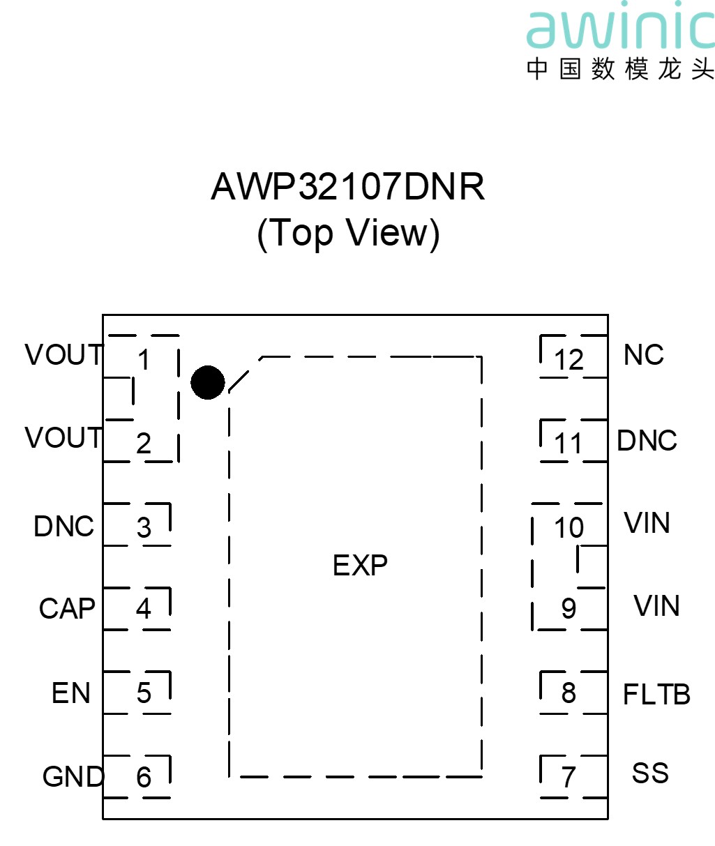
Figure 5 AWP32107DNR Package Information
– Top View
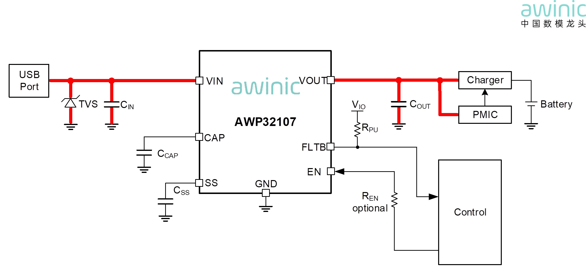
Figure 6 AWP32107DNR Typical Application
Block Diagram
Product Introduction – AWP32109DNR /
AWP32109S
·
Wide Input Voltage range from 3.4V to 32V
·
8A continuous current capability
·
VIN and VOUT are rated 38V Abs max
·
Integrated ultra‑low Ron switch: typ 17mΩ – AWP32109, typ
16mΩ – AWP32109S
·
Over‑Voltage Protection turn‑off response: typical 100ns
·
Ideal Diode RCP
·
Programmable soft‑start
·
VIN Under‑Voltage Lockout (UVLO)
·
Over‑Temperature Protection (OTP)
·
Short Circuit Protection
·
IEC 61000‑4‑2 Contact Discharge ±8KV
·
AWP32109: IEC 61000‑4‑5 45V Surge Protection on VIN and
VOUT
AWP32109S: IEC
61000‑4‑5 115V Surge Protection on VIN and 80V on VOUT
·
AWP32109DNR DFN3×3‑12L
AWP32109SDNR
DFN4×4‑16L
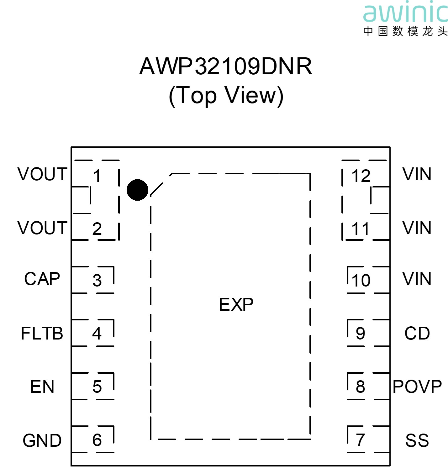
Figure 7 AWP32109DNR Package Information
– Top View
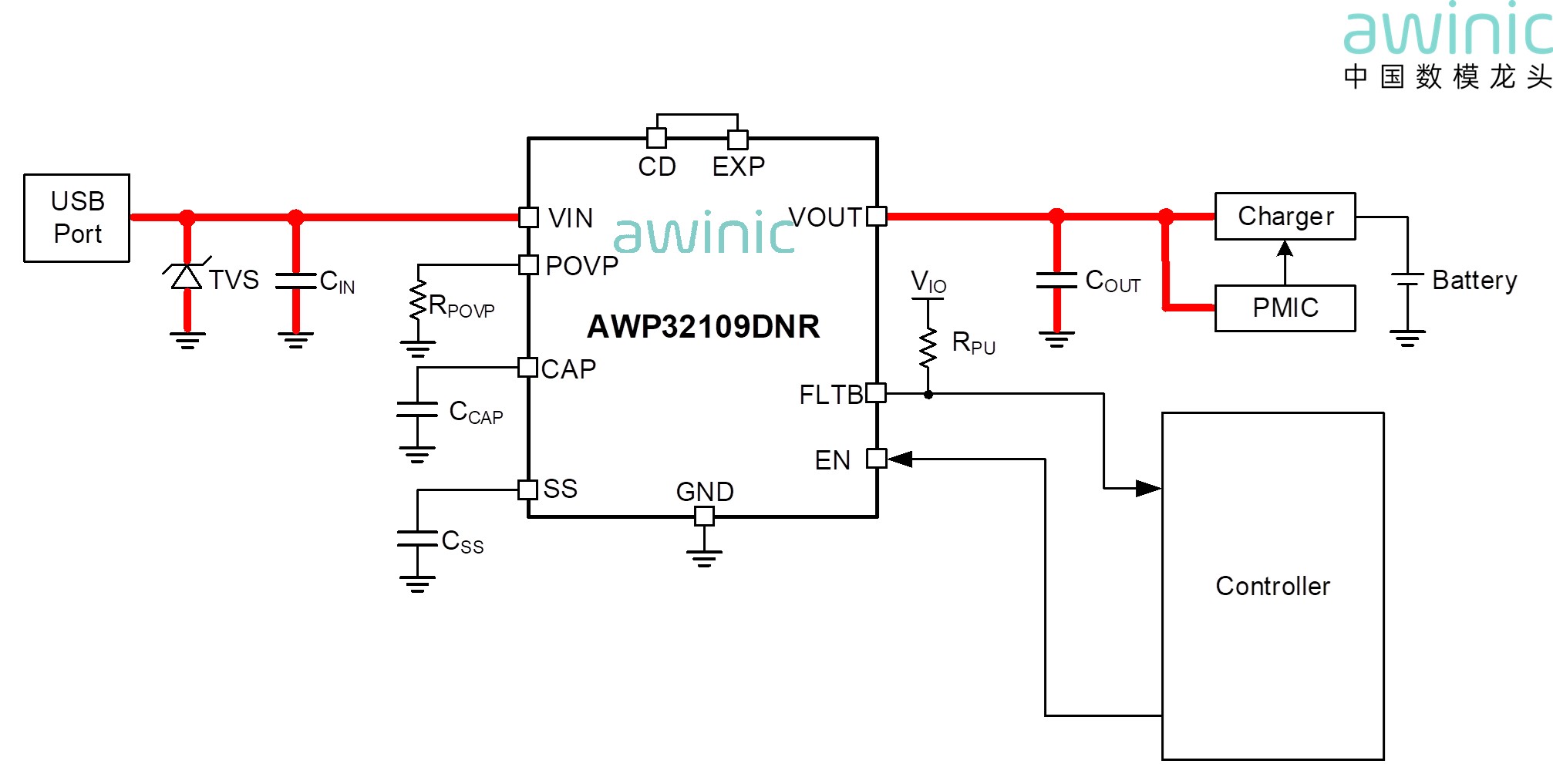
Figure 8 AWP32109DNR Typical Application
Block Diagram
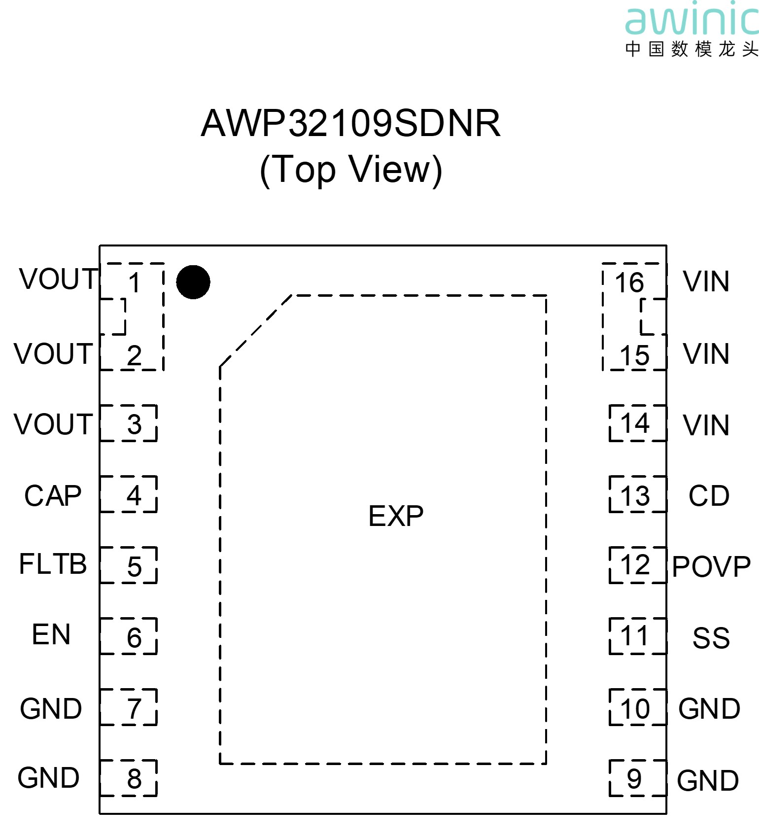
Figure 9 AWP32109SDNR Package
Information – Top View
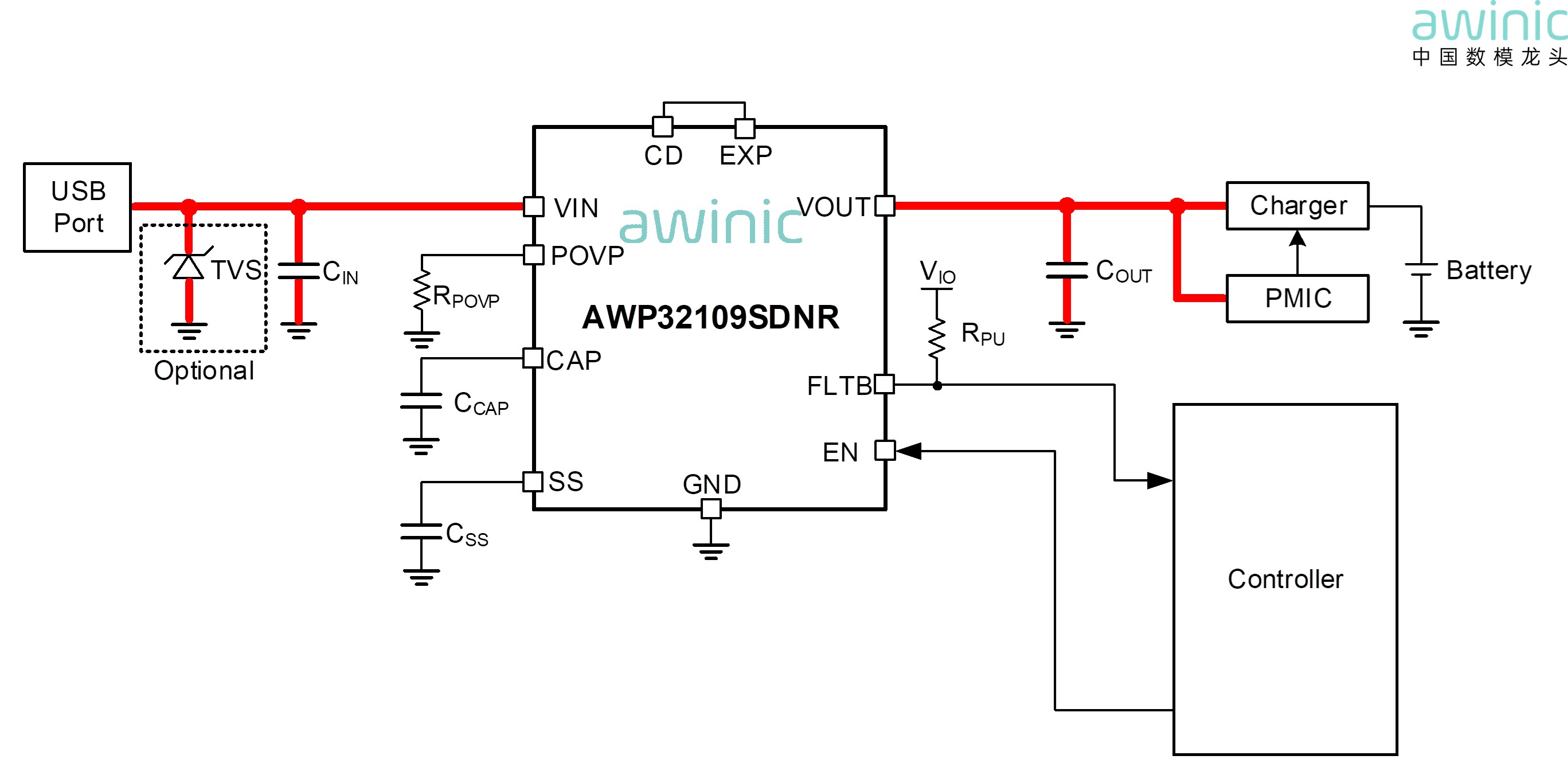
Figure 10 AWP32109SDNR Typical
Application Block Diagram
Typical Application Scenarios
Suitable for applications such as
laptops, docking stations, notebook expansion bases, etc.
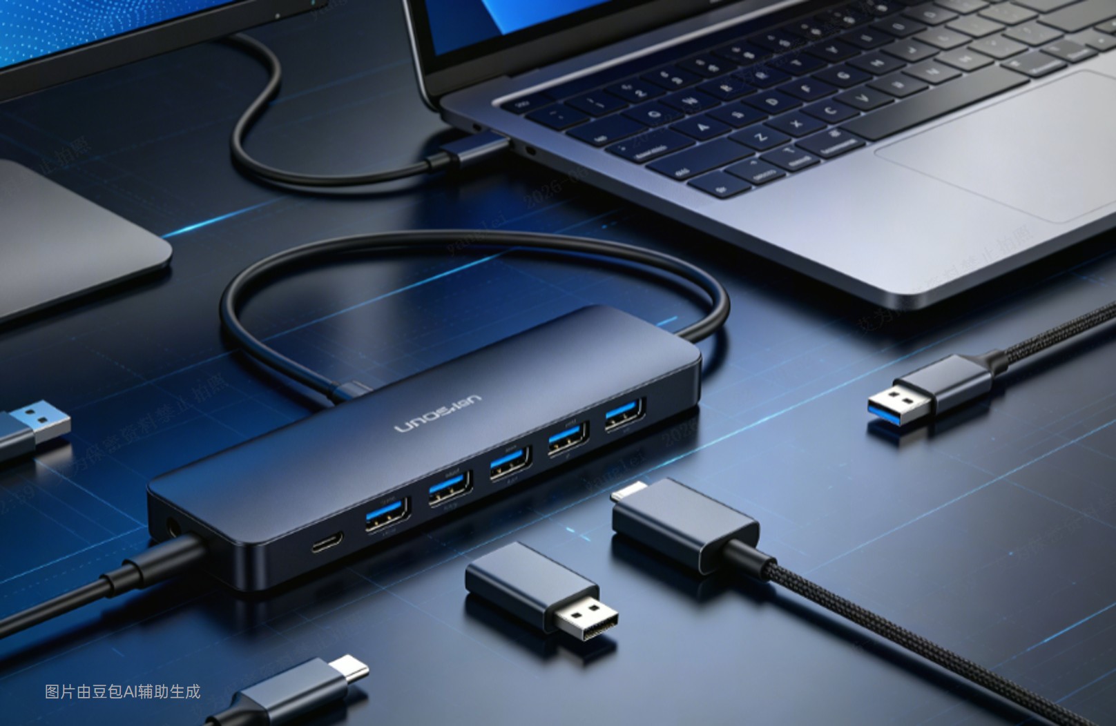
Figure 11 Application Scenario Example
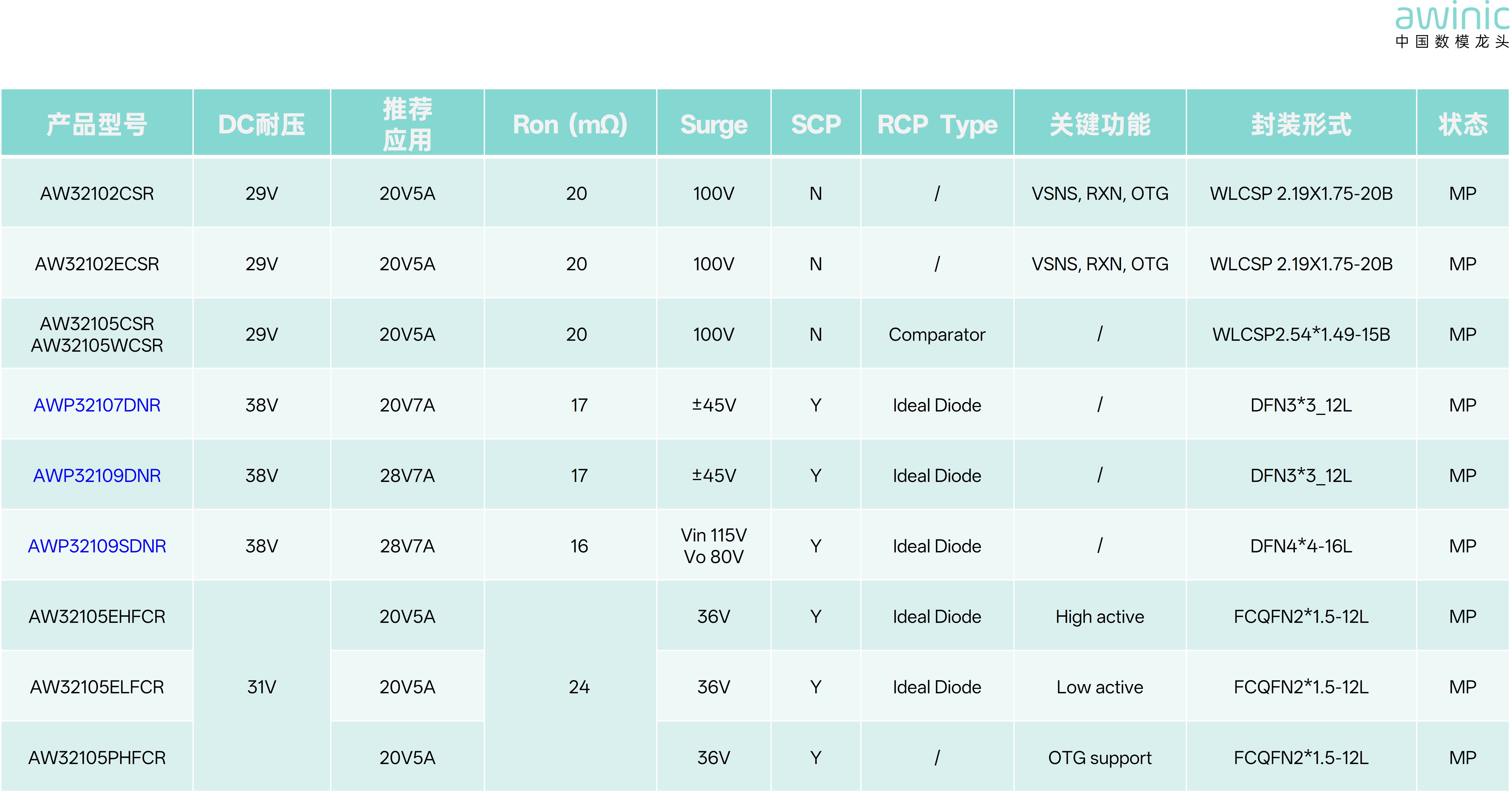
Table 1 AWINIC
Product Selection Guide