Many countries
around the world attach great importance to the value of broadcast emergency
communication: India (2023), Brazil (2021), Mexico (2017), and others have
mandated that mobile phones be equipped with FM radios and have them enabled by
default; the EU (2018) and Germany (2019) have legislated that new cars be
equipped with DAB digital broadcasting; the International Telecommunication
Union and other organizations have also continuously called on mobile phone manufacturers
to retain and enable FM functionality. Against this backdrop, China's GB
mandatory national standard for "In-Vehicle Wireless Broadcast Receiving
Systems" was officially project initiated at the end of April 2025. It is
expected to be released by the end of February 2027 and planned for mandatory
implementation by the end of February 2029, clearly stating that:
-
All
new domestic passenger and commercial vehicles (including new energy and
smart cockpit models) must be equipped with AM + FM broadcast systems; the
radio module cannot be omitted.
-
It
is strictly forbidden to provide only a software interface. Vehicles must
be equipped with a complete set of RF hardware, including an independent
broadcast antenna, LNA, mixing demodulation, etc.
In extreme
disaster scenarios, mobile communication base stations are highly susceptible
to paralysis. FM/DAB broadcasting, which consumes no data and does not rely on
base stations, serves as a critical safety net for emergency communication.
Traditional mobile phone FM has obvious shortcomings. Due to frequency band
characteristics, it relies on earphones to function as an antenna, resulting in
inconvenient use and limited experience. Addressing this industry pain point,
AWINIC Technology took the lead in 2011 by self-developing a dedicated FM LNA
chip. By achieving signal gain to share the built-in antenna, it eliminates the
dependence on an earphone antenna, supports native FM loudspeaker playback,
optimizes internal space design, and comprehensively improves the shortcomings
of traditional FM, earning widespread market recognition.
AWINIC has newly
iterated an automotive-grade broadcast LNA product that is compatible with
AM/FM/DAB multi-standard reception, providing a high-performance,
high-reliability domestic hardware solution for daily in-vehicle radio and
emergency broadcasting. Below is AWINIC's recommended LNA selection table:
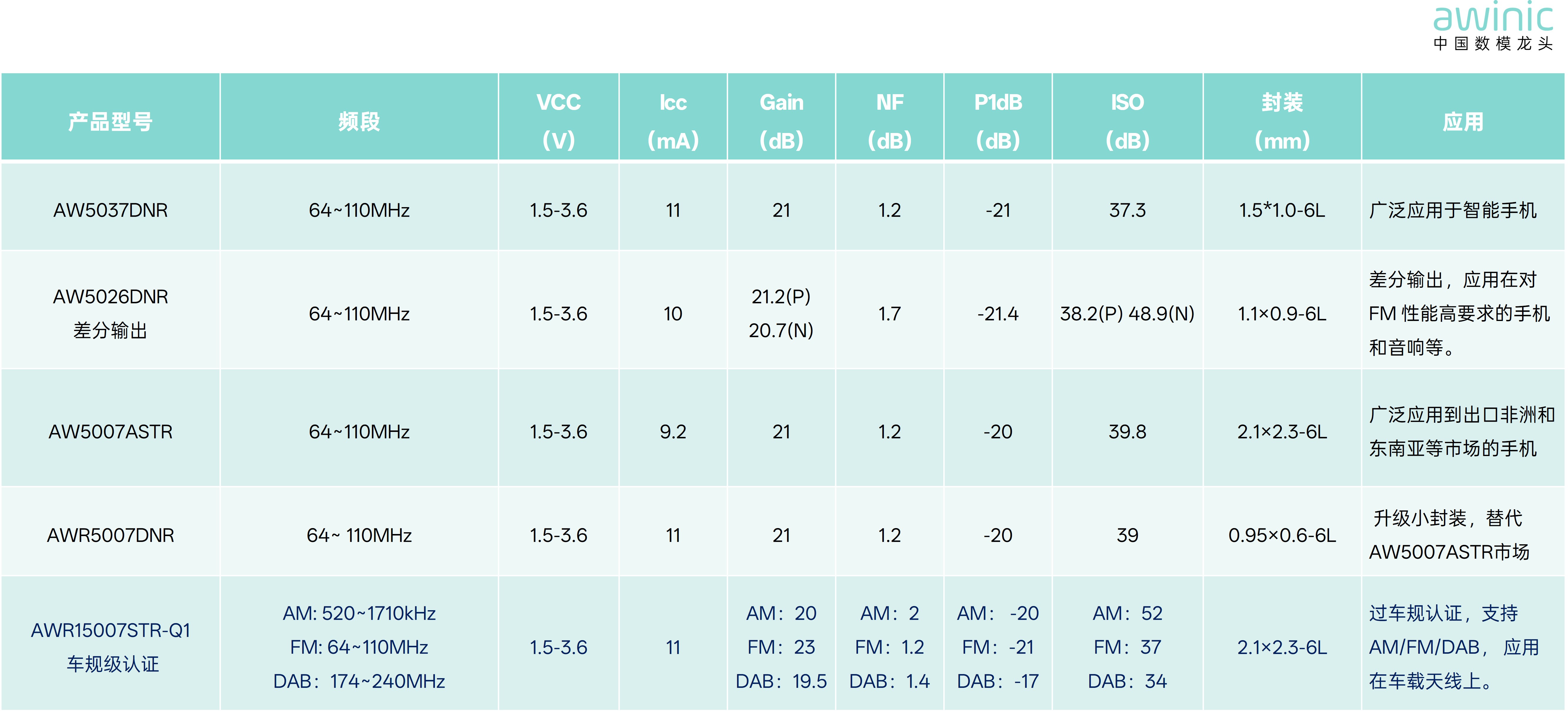
Table 1 AWINIC
Recommended LNA Selection Table
Implementing FM
functionality is not complex, but achieving outstanding sound quality and
reception experience is quite challenging. To achieve high-performance built-in
FM, this functionality must be given high priority during the product
definition stage.
The reference
design for EASY FM mobile phone applications is as follows:
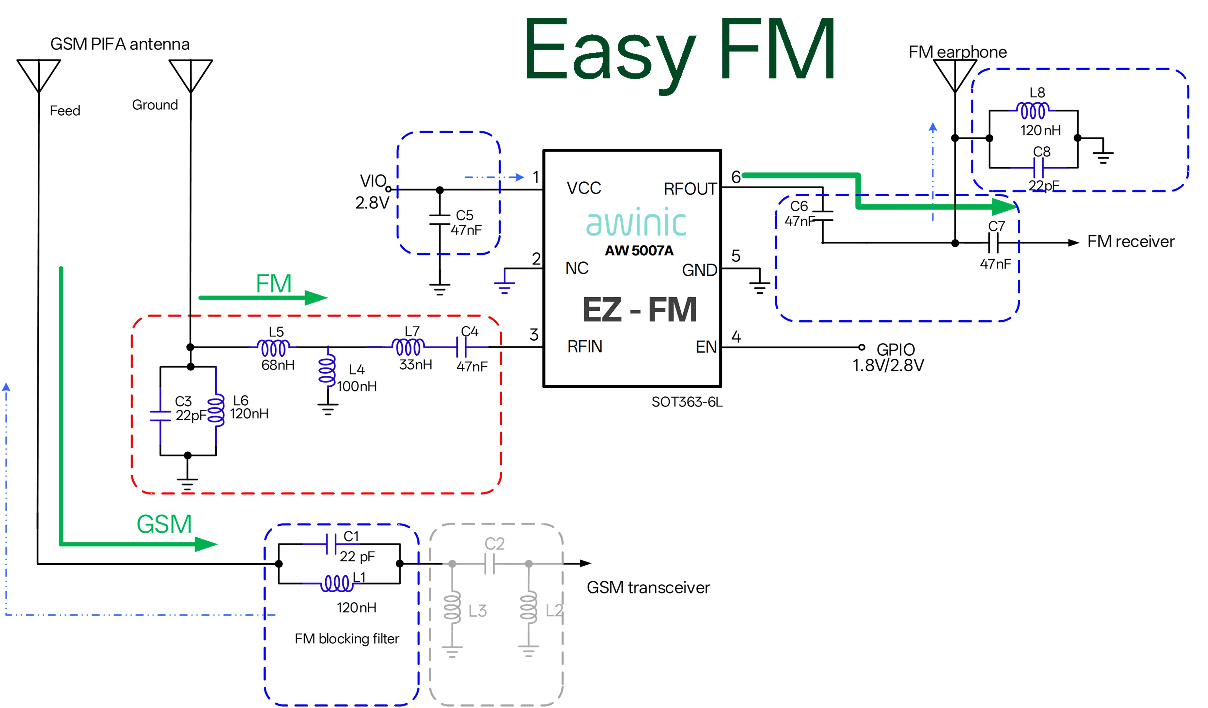
Figure 1 EASY FM
Mobile Phone Application Reference Diagram
01 Core FM Design
Considerations
I. To ensure
excellent performance of the FM receiving antenna, focus on the following key
design aspects:
-
Antenna
Length: Determines
FM signal reception efficiency.
-
Antenna
Width: Relates
to antenna radiation and reception capability, affecting overall receiving
sensitivity.
-
Clearance
Height: Affects
antenna resonance bandwidth, limiting the signal reception range.
-
Antenna
Plane: Single-plane
vs. multi-plane layouts change signal reception directivity, affecting
omnidirectional reception performance.
-
Operating
Environment: Avoid interference sources such as surrounding metal structures
and high-frequency components.
Case Examples
(Antenna Plane):
-
Single-plane
antenna: Poor
directivity.
-
Dual-plane
antenna: Better
directivity than single-plane.
-
Triple-plane
antenna: Best
directional compatibility.
II. FM has many
co-channel interference sources and needs to be kept away from all interference
sources, especially LCDs and audio PAs.
1. LCD
Interference Issues and Optimization Solutions
FM signal lines
should maintain a straight-line distance of more than 6mm from the LCD. Current
mobile phones mostly use full-screen designs, which shortens the distance
between the LCD and the antenna. LCDs (whether TFT or OLED) generate a large
amount of spurious interference signals during operation, which can easily
interfere with the main RF and FM reception, thereby reducing reception
performance. To effectively reduce LCD interference with the antenna, the
following measures should be taken during design:
-
Start
from the interference source: During the LCD selection phase, require
suppliers to control spurious interference during LCD operation and choose
LCD modules with low spurious emissions.
-
Shielding
measures: Add
electromagnetic shielding films or rear metal frames on the LCD module to
reduce the propagation of interference signals.
-
Physical
isolation: Keep
the antenna as far away from interference sources as possible; the greater
the distance, the less the interference.
-
Software
optimization: Many LCDs now support reducing interference through software
settings (such as spread spectrum, modifying clock frequency, LCD internal
operating frequency, etc.) to minimize spurious interference within the FM
band as much as possible.
2. Audio PA
Interference Issues and Optimization Solutions
Mobile phones
typically use Class D/K audio PAs. Their output signal is a PWM square wave,
which generates a large number of harmonic interferences. Therefore, it is
recommended to keep the FM antenna more than 15mm away from the audio PA and
add EMI filtering components (such as beads or LC inductors/capacitors) at the
interference source to suppress the spread of interference (e.g., the FB
position in Figure 2). When selecting EMI components, pay attention to the following
points:
-
Magnetic
Bead Selection: Prioritize magnetic beads that have minimal impact on audio
distortion (THD), while also choosing beads with higher impedance at
100MHz to enhance filtering effectiveness.
-
LC
Inductor/Capacitor Selection: A low-pass (audio) and high-impedance (FM) LC
filter can be designed at the FB position. In practical applications,
larger capacitors provide better interference suppression but increase
audio operating current, requiring a trade-off between effectiveness and
power consumption. Generally, inductors with larger inductance values are
chosen for this LC filter circuit whenever possible, though
high-inductance inductors significantly increase cost. Therefore, a
comprehensive trade-off is needed.
-
AWINIC
Solution: Using
a Class AB audio PA does not interfere with FM. The AW8155 is an audio PA
that supports both Class AB and Class D/K modes. By selecting Class D/K
mode for daily use and switching to Class AB mode during FM operation, the
issue of digital audio signals interfering with FM is perfectly resolved.
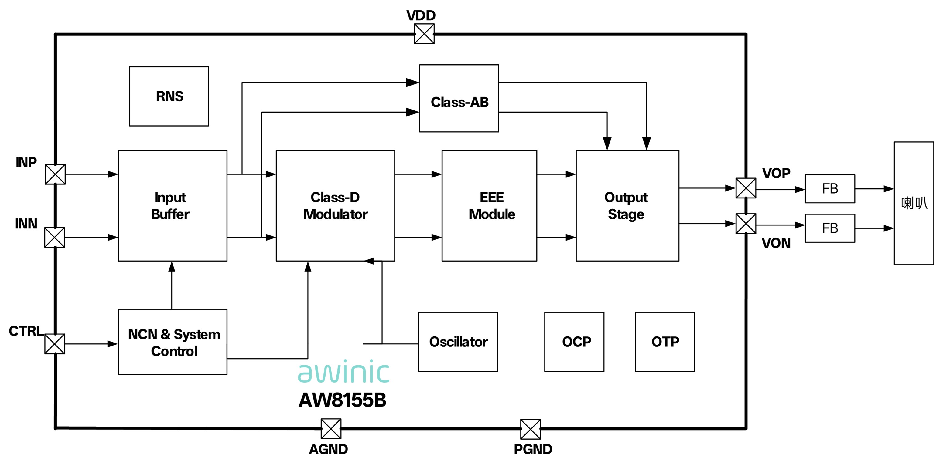
Figure 2 AW8155B
Functional Block Diagram
3. Other
Interference: NFC, etc.
When NFC
operates, a large portion of its harmonics fall within the FM band, causing
interference across the entire FM band. It is recommended to keep the NFC
antenna away from the FM antenna.
02 Application
Scenarios
III. Typical
Application Scenarios: Mobile Phone EASY FM and In-Vehicle Antenna
1. EASY FM in
Mobile Phone Applications
-
In
FM sharing GSM antenna applications, LC filtering effectiveness is very
important.
AWINIC
recommends the following two LC filter circuits as shown below:
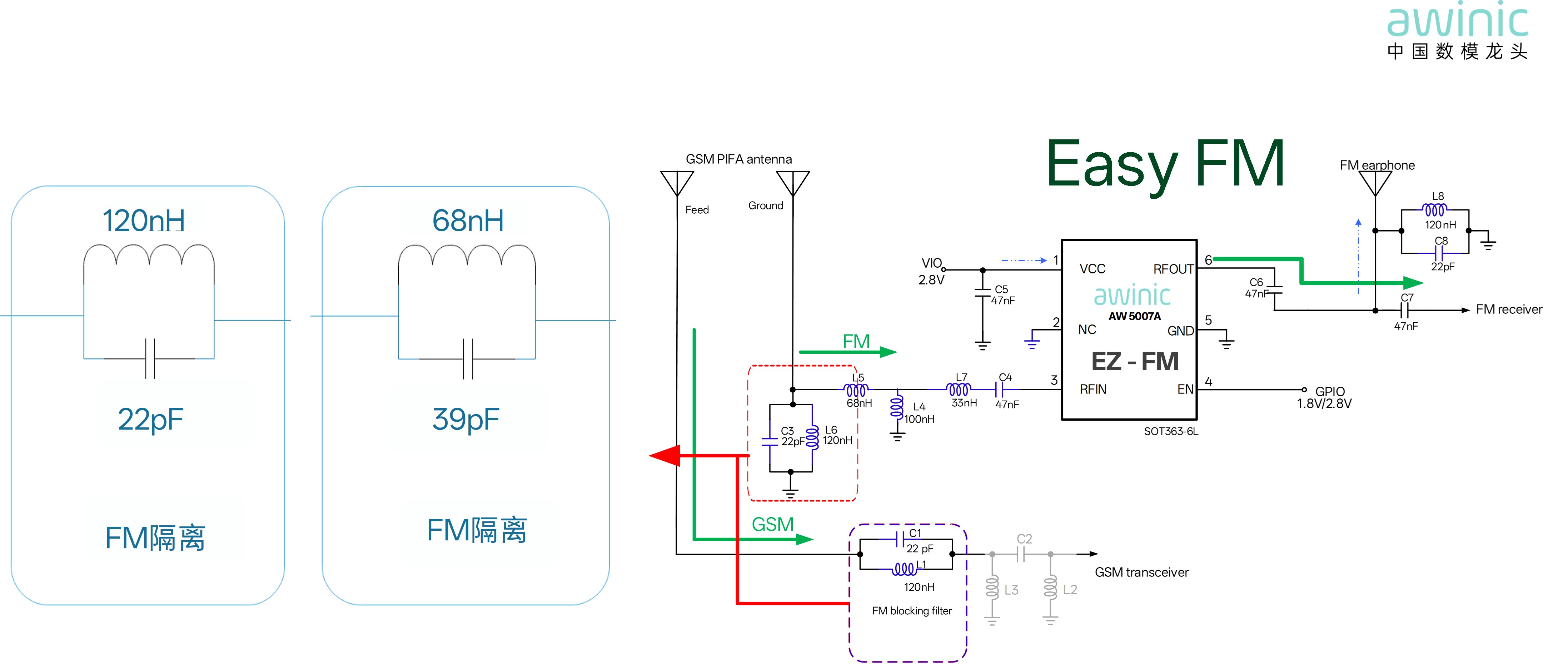
Figure 3 Two LC
Filter Circuit Diagrams
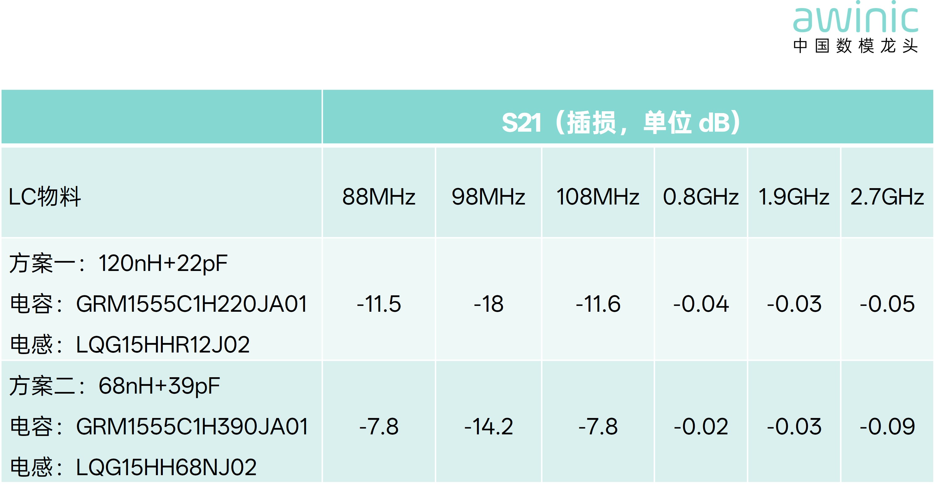
Table 2 Two LC
Filter Solution Tables
a) Recommended
priority: 120nH + 22pF parallel LC solution
Because 120nH
has a relatively high inductance value, small-package inductors have higher
DCR. It is recommended to use large-package, high-Q wire-wound inductors. In
practical applications, 0402 package inductors perform better than 0201. This
circuit has an insertion loss of only 0.03~0.05dB in the main mobile phone RF
band, which is negligible, while presenting high impedance characteristics in
the FM band (isolation: -11.5~-18dB), providing excellent isolation.
b) Alternative
solution: 68nH + 39pF
If structural
packaging limitations prevent the use of 0402 components and the 0201 package
lacks a 120nH inductor with low DCR, the 68nH+39pF solution can be substituted.
By reducing the inductance value and increasing the capacitance value, the
impact of inductor DCR is effectively minimized. This circuit has an insertion
loss of only 0.02~0.09dB in the main mobile phone RF band. FM isolation:
-7.8~-14.2dB, which is slightly attenuated but sufficient for constrained
scenarios.
2. Compatible
Earphone Antenna Design
Some customers
want to maximize the performance of both the built-in antenna and the earphone
antenna. To reduce signal attenuation caused by directly connecting the
built-in antenna and the earphone antenna in parallel, AWINIC's AW13412H switch
is used to switch the connection between the two antennas and the platform. For
differential configurations, a double-pole double-throw (DPDT) switch (AW35742)
can be used for switching, as shown in the figure below.
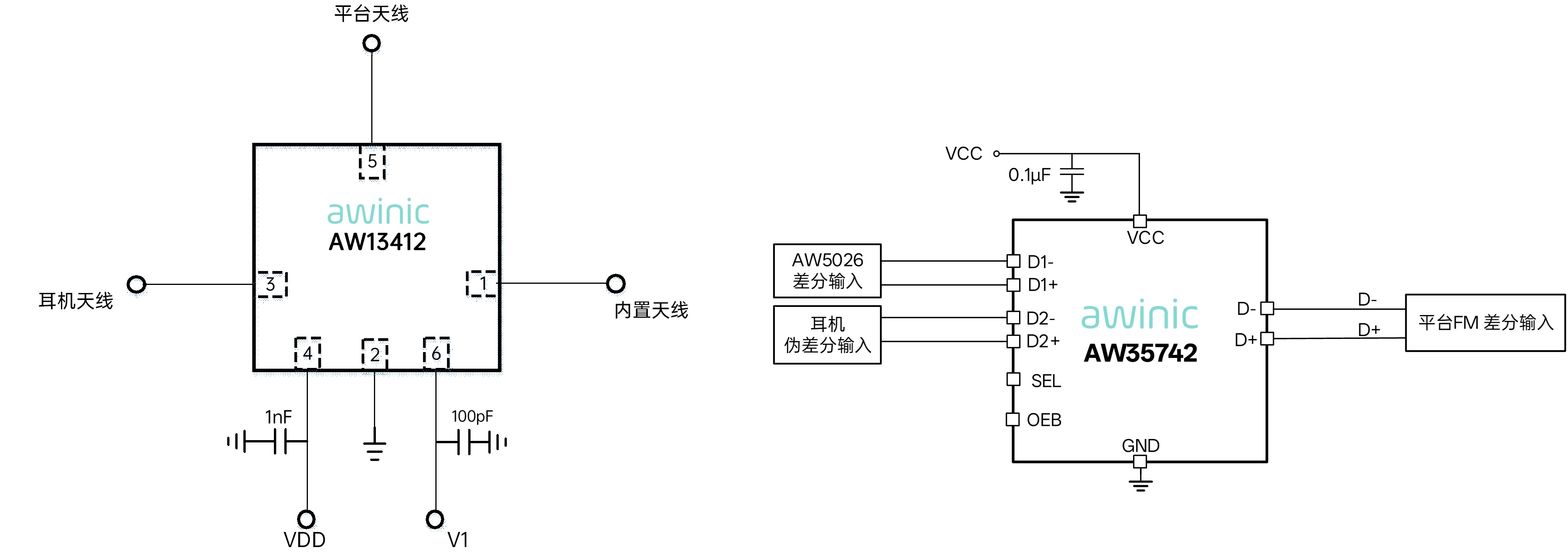
Figure 4
Differential Configuration Diagram
The following
shows the measured differences with and without the AW13412 for built-in and
earphone antennas:
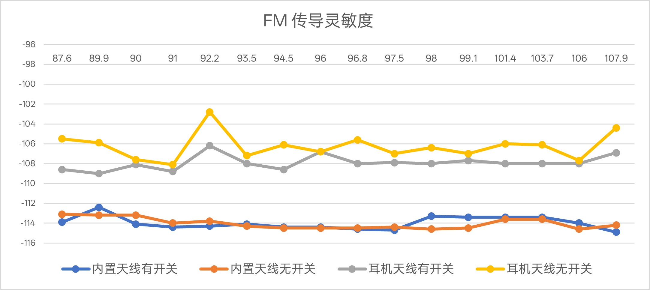
Figure 5
Difference Comparison Line Chart
2. FM-LNA
In-Vehicle Antenna Application
Factors such as
natural disasters and geopolitical conflicts can easily cause network
disruptions. Countries around the world are increasingly emphasizing the
construction of emergency broadcasting, and market demand for in-vehicle
antennas and receiving systems continues to grow. Current in-vehicle antenna
designs generally require compatibility with AM/FM/DAB multi-standard
reception. Following this industry trend, AWINIC has launched the
automotive-grade chip AWR15007STR-Q1, which fully supports AM, FM, and DAB all-format
broadcast reception, deeply adapting to the digital transformation needs of
in-vehicle broadcasting. A typical application scheme is shown in the figure
below.
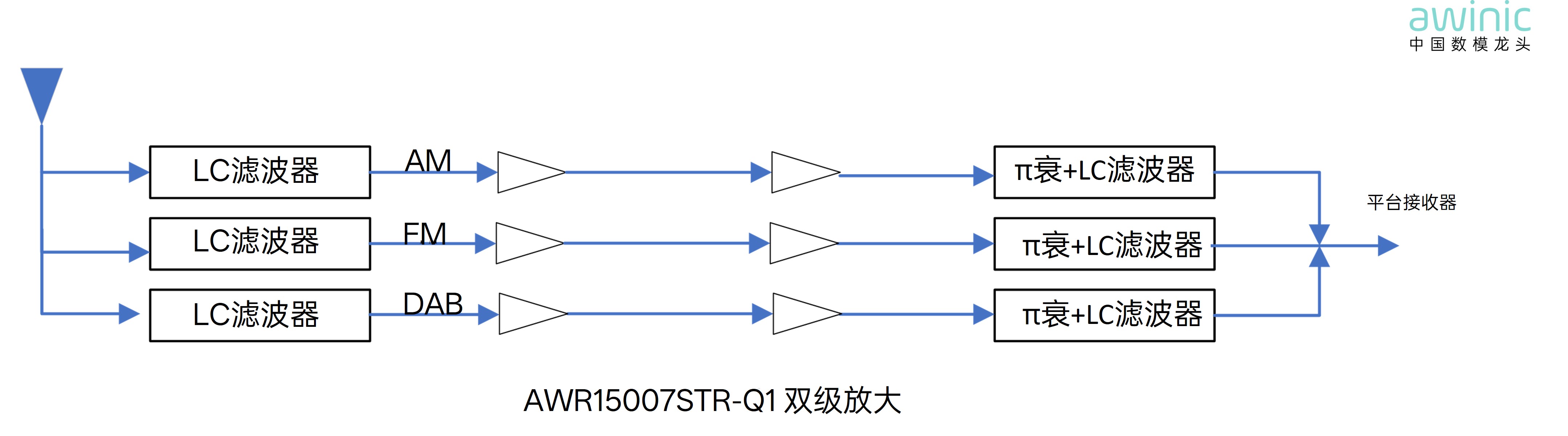
Figure 6
AWR15007STR-Q1 Application Schematic
The overall
operating frequency of AM/FM/DAB is relatively low, and the frequency bands are
densely arranged. System design needs to balance two core indicators:
efficiently suppressing out-of-band interference and improving band isolation,
while strictly controlling in-band insertion loss to ensure reception
sensitivity. Traditional LC filter circuits are difficult to tune. AWINIC's
automotive-grade high-gain broadcast LNA chip AWR15007STR-Q1 can effectively
compensate for signal loss caused by LC filtering and optimize reception
performance.
In summary,
AWINIC's broadcast reception products comprehensively cover two major
scenarios: mobile phones and in-vehicle systems. With high integration,
excellent RF performance, multi-scenario adaptability, and end-side AI
technology, then targetedly resolve industry design pain points. From LNA
device selection and electromagnetic interference suppression to filter
matching and antenna switching management, AWINIC provides a complete one-stop
RF solution. Whether for miniaturized built-in FM design in terminal devices or
for AM/FM/DAB digital broadcast upgrade needs in vehicles, AWINIC, with its
mature technical expertise and comprehensive product portfolio, ensures stable
and reliable broadcast signal reception, helps implement and improve emergency
broadcasting systems, fortifies public information communication links in
extreme scenarios, and safeguards the critical "lifeline radio
waves."